If you have ever swapped an SFP, QSFP, or SFP28 module and watched the link stay down, you already know the pain: transceiver compatibility is not only about “same form factor.” This guide helps network engineers and field technicians match fiber optic transceivers to specific switches using optics standards, vendor behavior, and measurable link checks. You will get a step-by-step implementation workflow, a decision checklist, and practical troubleshooting for the most common failure modes.
Prerequisites before you test transceiver compatibility

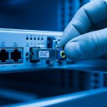
Before ordering optics, confirm you can validate compatibility end to end: hardware, optics parameters, and management behavior. In real deployments, the fastest path is to build a small “optics test kit” and document what your switch expects. This reduces rework when a module is electrically compatible but fails at the optics or DOM layer.
What you should gather
- Switch model and exact revision (for example, Cisco Catalyst 9300X, Nexus 9000, or an Arista 7050X). Record the running software version.
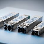
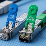
- Transceiver form factor: SFP, SFP+, SFP28, QSFP+, QSFP28, QSFP-DD, or CFP2. Confirm cage type in the switch.
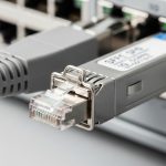
- Fiber type and link budget: OM3/OM4/OS2, connector type (LC/SC), and expected distance.
- Wavelength and data rate: for example, 10G-SR is typically 850 nm multimode, while 10G-LR is 1310 nm single-mode.
- DOM expectations: whether the switch polls Digital Optical Monitoring (DOM) over I2C and what alarms it raises.
- Operating environment: rack temperature profile and airflow limits. Many modules have 0 to 70 C or -40 to 85 C variants.
Step-by-step workflow to validate transceiver compatibility
This section is an implementation guide you can follow during a change window. The goal is to verify compatibility before you commit to bulk replacement, and to isolate whether failures are caused by optics, DOM, power, or switch policy. Use the steps in order and record outcomes for each module.
Confirm the optics standard and lane rate match
Start with the physical and electrical layer: the switch expects a specific standard, not just “10G.” For example, a switch that supports 10GBASE-SR will not treat a module programmed for a different standard as valid even if the optics are similar. Match both data rate and wavelength to the switch’s intended mode.
Use vendor documentation and IEEE alignment: 10GBASE-SR and 10GBASE-LR are standardized in the IEEE Ethernet PHY family, with optical performance requirements documented in the relevant IEEE 802.3 clauses. For baseline behavior, reference [Source: IEEE 802.3] and the switch vendor’s SFP/QSFP installation guide.
Expected outcome: You can map the switch port to the correct module type (for example, 10G-SR vs 10G-LR) and wavelength band (850 nm vs 1310 nm vs 1550 nm).
Verify distance and fiber type with an actual link budget
Compatibility failures often happen because the module is “the right type” but the link budget is exceeded. Build a quick budget using fiber attenuation, patch cord loss, splice loss, and connector insertion loss. Then compare it to the module’s specified reach and power levels.
Example: if your OM4 plant is 220 m from ToR A to ToR B, and you have two patch cords (0.5 dB each) plus 0.3 dB per connector pair, your total loss may still fit within typical 10G-SR reach specifications for OM4. But if you mix OM3 cables or add more connectors, the margin disappears even though the module “inserts fine.”
Expected outcome: You have a documented loss estimate that stays within the module’s guaranteed optical performance for your fiber type.
Check module identity, part numbers, and switch policy
Many enterprise switches enforce “known good” transceiver lists or apply thresholds based on module ID and DOM data. Even when the module is electrically standards-compliant, a switch may mark it “unsupported” or keep the port in an error state.
Practical approach: consult the switch’s optics compatibility matrix and ensure the module vendor or OEM is listed. If you are using third-party optics, validate that the module is explicitly designed for your platform and that it provides matching DOM behavior.
For optical components, include real module families in your evaluation, such as:
- For 10G-SR multimode: Cisco-approved optics often align with modules like Cisco SFP-10G-SR, and third-party 10GSR optics such as Finisar FTLX8571D3BCL or FS.com SFP-10GSR-85 (verify exact DOM and temperature grade).
- For 25G SR on SFP28: confirm the switch supports 25GBASE-SR and that the module’s wavelength and reach match OM4 requirements.
Expected outcome: You identify whether the switch expects a specific module family, and you reduce risk by selecting optics with proven platform alignment.
Validate DOM support and read alarms before bringing up traffic
DOM is where many “it should work” swaps fail. DOM data is transported via I2C and includes temperature, supply voltage, bias current, and received optical power. Some switches also check for vendor-specific thresholds or interpret missing DOM fields as invalid.
On Cisco-like platforms, operators commonly use CLI to check module presence and transceiver diagnostics. Exact commands vary by OS, but the workflow is consistent: confirm module status, confirm DOM sensor readings are sane (not all zeros, no I2C errors), and ensure no “unsupported transceiver” alarms appear.
Expected outcome: DOM reads successfully and the port reports “link up possible” or “transceiver present” without policy errors.
Confirm power class and thermal behavior
Transceiver compatibility includes power draw and thermal limits. QSFP/QSFP28 modules can have different power budgets and may require specific cooling airflow. If your rack is near the upper temperature bound, the module may throttle or fail link training.
Validate that your module’s operating range matches the environment. If the switch runs in a constrained airflow zone, prioritize -40 to 85 C industrial-grade modules for mission-critical links.
Expected outcome: The module operates within rated temperature and does not produce intermittent DOM faults under sustained load.
Bring up link using controlled verification
Test in a controlled manner: first establish link without heavy traffic, then validate error counters and optics thresholds. If you have a spare patch cord, test with a known-good fiber segment to separate fiber issues from module issues. After link is stable, run traffic and confirm no rising CRC or FEC-related errors.
Expected outcome: Link stays up, error counters remain stable, and DOM readings remain within acceptable ranges.
Key specification comparison that drives transceiver compatibility
To match optics to switches, you must compare parameters that directly affect link establishment. The most important are data rate, wavelength, reach by fiber type, connector interface, DOM feature set, and operating temperature. Below is a practical comparison for common enterprise scenarios.
| Transceiver type | Typical wavelength | Target data rate | Typical reach (multimode) | Typical reach (single-mode) | Connector | DOM | Operating temperature |
|---|---|---|---|---|---|---|---|
| SFP-10G-SR | 850 nm | 10G | Up to ~300 m on OM4 (varies by vendor) | N/A | LC (common) | Usually supported | Often 0 to 70 C or -40 to 85 C |
| SFP-10G-LR | 1310 nm | 10G | N/A | Up to ~10 km (varies by vendor) | LC (common) | Usually supported | Often 0 to 70 C or -40 to 85 C |
| SFP28-25G-SR | 850 nm | 25G | Up to ~100 m on OM4 (varies by vendor) | N/A | LC (common) | Usually supported | Often 0 to 70 C or -40 to 85 C |
| QSFP28-100G-SR4 | 850 nm (4 lanes) | 100G | Up to ~100 m on OM4 (varies by vendor) | N/A | MPO/MTP | Usually supported | Often 0 to 70 C or -40 to 85 C |
Compatibility note: Even within the same “SR” label, vendors can differ in DOM alarm thresholds, transmitter power levels, and internal calibration. Those differences are usually manageable, but strict switch policy enforcement can still block third-party modules.
Sources: [Source: IEEE 802.3], [Source: Vendor transceiver datasheets], [Source: ANSI/TIA-568 optical cabling guidance via vendor implementations].
Decision checklist engineers use for transceiver compatibility
Use this ordered checklist during planning and during the actual swap. It mirrors what field teams do to minimize downtime and avoid trial-and-error. Keep the results in a spreadsheet so future swaps become faster.
- Distance vs reach: confirm fiber type (OM3/OM4/OS2) and compute expected loss and margin.
- Data rate and lane mapping: ensure the switch port supports the exact Ethernet PHY mode (for example, 25GBASE-SR vs 25GBASE-LR).
- Wavelength alignment: verify 850 nm vs 1310 nm vs 1550 nm. Do not assume “SR means multimode” on every platform.
- Connector and polarity: LC vs MPO, and MPO polarity method (Type A vs Type B) for multi-fiber links.
- Switch compatibility matrix: prefer modules explicitly listed by the switch vendor.
- DOM support and sensor behavior: confirm DOM is present and that the switch can read it via I2C without errors.
- Operating temperature: match your environment and airflow constraints; avoid mixing industrial and consumer-grade without checking.
- Power budget: confirm module power draw fits the switch’s thermal and electrical design for that cage type.
- Vendor lock-in risk: if you use third-party optics, validate for your specific model and software release; re-validate after upgrades.
Pro Tip: In many field cases, the “unsupported transceiver” message is not caused by optics wavelength or reach at all. It is triggered by DOM identity or alarm-threshold mismatch, where the switch reads valid sensor values but flags the module based on vendor ID or calibration ranges. If you can access DOM readings, compare temperature, bias current, and received power trends between a known-good OEM module and the candidate third-party module.
Common mistakes and troubleshooting for transceiver compatibility
When a link fails, resist the urge to blame the fiber first. Most real failures fall into a few repeatable categories. Below are the top pitfalls with root causes and corrective actions.
Pitfall 1: Wrong module type that “physically fits”
Root cause: The module matches the form factor but not the PHY mode or wavelength band. Example: inserting an SFP-10G-LR (1310 nm) into a port configured for SR optics expectations, or mixing SR and LR in a way that breaks link training.
Solution: Confirm the port’s intended standard in the switch configuration and match wavelength and data rate. Check the transceiver label and vendor datasheet for wavelength and compliance. If the switch has a “transceiver type” display, verify it reports the expected class.
Pitfall 2: DOM polling errors leading to “unsupported” or no-link
Root cause: The switch cannot read DOM over I2C, or DOM thresholds do not align with the switch’s policy. This can happen with incompatible third-party modules, counterfeit optics, or modules with incomplete EEPROM fields.
Solution: Use the switch CLI to inspect module status and DOM diagnostics. If you see I2C errors or missing sensor values, replace with an OEM-listed module or a third-party module explicitly validated for that platform. Re-test after a switch software upgrade, because DOM handling can change.
Pitfall 3: Fiber polarity and connector mismatch on MPO links
Root cause: For multi-fiber transceivers like QSFP28-100G-SR4, MPO polarity mismatches can prevent correct lane pairing. Symptoms include link flaps, high error rates, or persistent “link up but unusable” behavior.
Solution: Verify MPO polarity method end-to-end, then correct using polarity adapters or re-termination. Test with known-good patch cords and confirm that the receive lanes are connected to the correct transmit lanes.
Pitfall 4: Exceeding link budget with “near the limit” optics
Root cause: A module rated for a certain reach is installed on a link with higher attenuation due to additional connectors, dirty fiber, or aging. The link may come up briefly then degrade.
Solution: Clean connectors using approved fiber cleaning tools, then re-run the link test. Measure optical power if available and compare candidate module DOM received power against the known-good baseline. Reduce the number of patch cord segments or replace high-loss components.
Expected outcome: You can pinpoint whether the failure is standard mismatch, DOM policy, polarity, or optical budget, and you restore stable link operation quickly.
Cost and ROI considerations for transceiver compatibility
Transceiver pricing varies widely by speed, reach, and whether you choose OEM or third-party. As a realistic planning baseline, common enterprise optics often fall into these ranges (street pricing varies by region and procurement channel):
- 10G-SR SFP+: roughly $50 to $200 per module for OEM or validated third-party.
- 25G-SR SFP28: roughly $120 to $350 per module.
- 100G-SR QSFP28: roughly $400 to $1,200 per module depending on OM4 reach and vendor.
TCO matters more than purchase price. Third-party optics can reduce upfront cost, but you may pay in engineering time, additional spares, and re-validation during switch upgrades. If failure rates or compatibility incidents increase, the ROI can reverse quickly.
Recommendation: Calculate TCO using expected lifespan, warranty terms, and change control overhead. If your environment is safety-critical or uptime-critical, bias toward modules that are explicitly validated for your switch models to reduce operational risk.
FAQ on transceiver compatibility for real switch ports
How do I confirm transceiver compatibility for a specific switch model?
Start with the switch’s optics compatibility matrix and match module type, wavelength, and data rate. Then validate by inserting a known-good OEM module and reading DOM diagnostics. If you use third-party optics, select models explicitly validated for your platform and software version.
Can I use third-party transceivers if the connector and wavelength match?
Sometimes yes, but not always. Even with correct wavelength and reach, switch policy and DOM identity thresholds can mark a module as unsupported. The safest approach is to test one module in a maintenance window, compare DOM readings to a known-good OEM unit, and then scale only after stability is confirmed.
Why does my link stay down even though the module is detected?
Common causes include PHY standard mismatch, fiber polarity issues (especially MPO for 100G), or exceeding the link budget due to extra loss. Check interface state, DOM alarms, and received optical power. If possible, test with a known-good patch cord and a known-good module to isolate the fault.
What DOM readings should I look at during transceiver compatibility testing?
Look for stable temperature and supply voltage, reasonable bias current, and received optical power that tracks expected levels for your link. Also watch for I2C errors or missing sensor fields. A module can be physically present but still fail due to DOM policy interpretation.
Will transceiver compatibility break after a switch software upgrade?
It can. Switch OS updates sometimes adjust transceiver validation behavior, threshold interpretation, or DOM handling. If you rely on third-party optics, re-validate critical links after upgrades and keep spares of your known-good modules.
What is the fastest troubleshooting path when a new optic fails?
Replace with a known-good OEM module first to prove the port and fiber are functional. If the port works with OEM, then the issue is likely third-party DOM identity or calibration thresholds. If even OEM fails, focus on fiber polarity, connector cleanliness, or link budget.
Transceiver compatibility is a system-level problem: matching form factor is only the beginning. By following a disciplined workflow that verifies standard alignment, link budget, DOM behavior, and switch policy, you can reduce downtime and avoid expensive rework. Next step: review transceiver DOM validation to strengthen your testing process before production rollout.
Author bio: I have deployed and validated SFP, SFP28, QSFP+, and QSFP28 optics across enterprise data centers, using DOM telemetry and interface error counters to confirm link integrity. I work at the intersection of fiber engineering and switch operational procedures, with a focus on measurable compatibility outcomes.