When a data center moves from 100G to 400G, the riskiest part is often not routing or switching, but the optical layer. This guide helps network and facilities teams choose the right transceivers, validate switch compatibility, and avoid avoidable link failures during a staged rollout. You will get a practical checklist, a spec comparison table, and troubleshooting patterns seen in live deployments.
Planning the optics for a 100G to 400G upgrade: what must be true first
Before you buy modules, confirm that the target switches, optics cages, and cabling plant support the same physical layer and lane configuration expected by your upgrade path. Most 100G to 400G upgrades in leaf-spine designs use 400G pluggables that map to either 8x50G (common with QSFP-DD/OSFP) or vendor-specific lane groupings that must match the switch’s firmware and port mode. If the switch runs a different electrical interface mode than the module expects, the link may train down, show high CRC/BER, or fail to come up.
Also validate the cabling distance budget end to end: transceiver optical power, receiver sensitivity, fiber attenuation at the module wavelength, and patch cord losses. Use vendor link budget calculators (and keep a margin for aging and cleaning variability). For standards context, the physical layer behavior is aligned with IEEE 802.3 optical interface families; check the exact clause for your data rate and form factor at IEEE 802.3 optical interfaces and the module’s datasheet.

Key transceiver options for 100G to 400G upgrade: SR, LR, DR, and ER
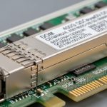
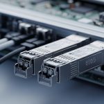
For data centers, the dominant decision is usually whether you are staying on multimode fiber (MMF) or moving to single-mode fiber (SMF). SR variants are typically designed for MMF over short reach, while LR and beyond are for SMF over longer distances. At 400G, pluggable families commonly include QSFP-DD and OSFP; the exact reach depends on wavelength, optics generation, and fiber type.
In practice, you will see common optics such as:
- 100G SR4 (4 lanes aggregate) for older 100G ports.
- 400G SR8 (8 lanes aggregate) for MMF within the data hall.
- 400G LR8 (8 lanes aggregate) for SMF where patching spans rows or pods.
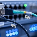
When you keep the same fiber type and mostly swap the port speed, you reduce risk. When you change from MMF to SMF, you must treat the cabling plant as a separate project: connectors, jumpers, and MPO polarity or fanout handling can dominate outage time.
| Module type | Typical data rate | Wavelength | Target fiber | Reach (typical) | Form factor / connector | Operating temp (typical) |
|---|---|---|---|---|---|---|
| Cisco SFP-10G-SR / 100G SR4 class (example family) | 100G | 850 nm | MMF (OM4/OM5) | ~100 m to ~150 m (depends on OM class and module spec) | QSFP28 (100G SR4) | 0 to 70 C or -5 to 85 C (varies by vendor) |
| 400G SR8 class | 400G | 850 nm | MMF (OM4/OM5) | ~100 m to ~150 m (vendor-defined) | QSFP-DD or OSFP (8-lane) | 0 to 70 C or -5 to 85 C |
| 400G LR8 class | 400G | 1310 nm | SMF (single-mode) | ~10 km (vendor-defined) | QSFP-DD or OSFP (8-lane) | 0 to 70 C or -5 to 85 C |
| 400G DR4/FR4 class (where used) | 400G | 1310/1550 nm bands (varies) | SMF | ~2 km to ~2+ km (varies by spec) | QSFP-DD | 0 to 70 C or -5 to 85 C |
Note: Reach and temperature range vary by vendor and exact part number. Always use the specific datasheet for the module model you plan to deploy. For concrete examples, check vendor datasheets such as Finisar/II-VI families like Lumentum optical transceiver datasheets and FS.com product pages for specific module SKUs like FS.com transceiver specifications.
Pro Tip: In many “it should work” upgrades, the real cause is not optics reach but port mode mismatches. Verify the switch’s port profile for 400G (lane map, FEC requirement, and breakout rules) before swapping modules; otherwise the module may train but run at a degraded mode with elevated errors.
Real-world deployment scenario: staged 100G to 400G in a leaf-spine fabric
In a typical rollout, a team upgrades a 3-tier data center leaf-spine topology where each ToR switch has 48 downlink ports and 8 uplinks. Suppose the original fabric uses 100G uplinks to spines with QSFP28 SR4 on MMF OM4, with an average link distance of 55 m including patch cords. The upgrade plan replaces uplinks first: each spine pair gains 400G uplinks, moving from 8x100G to 2x400G per direction, reducing total port count while maintaining capacity.
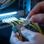
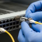
Operationally, the team budgets for 400G SR8 within the same MMF zone to avoid a cabling rebuild. They inventory patch cord lengths and confirm connector cleanliness using inspection tools, then validate transceiver DOM telemetry after insertion: optical power (Tx), bias current, and temperature should be within the datasheet’s thresholds. During the cutover window, they stage one leaf at a time, monitor interface counters for CRC/BER indicators, and only expand once link stability matches baseline behavior.
Selection checklist for 100G to 400G upgrade optics: what engineers verify
Use this ordered decision checklist to reduce incompatibility surprises. Treat it as a pre-purchase gate and again as a pre-install gate.
- Distance budget: confirm fiber type (OM4/OM5 vs OS2), patch cord lengths, and expected attenuation; keep margin for cleaning and connector variability.
- Switch compatibility: match form factor (QSFP-DD or OSFP) and verify the exact port mode supported by the switch firmware.
- Optical reach class: choose SR vs LR based on planned spans; do not assume “MMF is short” if patch cords and trays add loss.
- DOM support and monitoring: confirm the switch reads standard DOM fields (temperature, bias, Tx/Rx power) and that the vendor’s implementation is compatible.
- FEC requirements: if your platform mandates FEC, ensure the module supports the same FEC mode; otherwise you may see link instability.
- Operating temperature: validate module temperature range against the actual intake air temperature and airflow pattern at the rack.
- Vendor lock-in risk: check if the switch enforces vendor/part-number allowlists; plan for certified third-party options if OEM lead times are long.
Common pitfalls and troubleshooting during a 100G to 400G upgrade
Most failures fall into a small set of repeatable patterns. Here are concrete issues, root causes, and fixes seen during field cutovers.
Link does not come up after module insertion
Root cause: Port mode mismatch or unsupported lane mapping for 400G. Some switches require a specific profile before 400G optics will train correctly.
Solution: Set the port profile to the correct 400G mode, confirm breakout settings are disabled/enabled as required, then reinsert the module. If still failing, test the module in a known-good port and compare DOM events.
High error counters (CRC, FEC corrected errors) under load
Root cause: Fiber polarity or MPO alignment issue, or connector contamination causing optical power penalty. With lane-based optics, a single misaligned lane can trigger sustained BER.
Solution: Inspect connectors with an endoscope, clean with approved methods, then verify MPO polarity or fanout mapping. Swap jumpers with a known-good patch to isolate the problem to optics vs cabling.
Intermittent link drops after airflow changes or during maintenance
Root cause: Thermal margin too tight. Some racks run hotter during door-open or containment reconfiguration, driving module temperature out of spec.
Solution: Measure intake and exhaust temperatures at the rack and compare to the module operating range. Improve airflow, reseat adjacent modules to avoid airflow obstruction, and confirm the transceiver reports temperature within thresholds.
Works at idle but fails during line-rate testing
Root cause: Inadequate distance margin or unaccounted patch cord loss. Link budgets that look fine at low utilization can collapse at full-rate due to receiver sensitivity limits.
Solution: Recalculate the budget using measured fiber attenuation and patch cord specs. If needed, shorten jumpers, move to a higher-reach optics class (for SMF), or reduce splits in the path.
Cost and ROI note: budgeting the 100G to 400G upgrade without surprises
Typical street pricing varies heavily by reach and certification. As a practical planning range, 400G SR8 modules often cost more than legacy 100G optics but are frequently cheaper per bit than long-reach SMF options. OEM-branded optics can carry a premium of roughly 20% to 60% versus widely compatible third-party modules, though the exact delta depends on lead time and vendor certification.
For ROI, include total cost of ownership: module purchase price, expected failure rate, spares inventory, and downtime cost during cutovers. A common approach is to buy a small “pilot batch” (for each reach type) plus spares sized to your maintenance SLA. If your environment uses strict allowlists, OEM or certified third-party can materially reduce the risk of rework and expedite approvals.

FAQ: 100G to 400G upgrade optics questions engineers ask
What fiber type should I choose for a 100G to 400G upgrade?
If you already have OM4/OM5 with short spans and predictable patch cord lengths, 400G SR8 is often the lowest-risk path. If spans exceed SR reach or you need longer inter-pod distance, plan for 400G LR8 on OS2 single-mode fiber.
How do I confirm switch compatibility before ordering?
Check the switch vendor’s optics compatibility matrix for your exact model and firmware version. Then validate port mode and FEC settings during a pilot installation, not just by “form factor match.”
Will third-party optics work in a 100G to 400G upgrade?
Often they do, but compatibility depends on vendor allowlists, DOM implementation, and the switch’s enforcement policy. Use a pilot batch and monitor DOM telemetry and error counters under load before scaling.
What DOM telemetry should I monitor after insertion?
Focus on module temperature, Tx bias current, Tx/Rx optical power, and any threshold alarms reported by the switch. If Tx power is low or Rx power is near sensitivity, treat it as a cabling or cleanliness issue first.
Why do I see link flaps only during peak traffic?
Peak traffic stresses signal integrity and can reveal marginal distance budgets or thermal headroom. Recheck link budget math, inspect connectors, and verify module temperature during the same peak window.
What is the fastest safe rollout strategy?
Upgrade one pod or one leaf at a time, using a pilot batch and a rollback plan. Keep spares for each reach type and pre-stage patch cords so you can isolate optics vs cabling within minutes.
For your next step, map your current uplink distances and port modes, then build a module shortlist using the same checklist above with a pilot batch plan. If you need related guidance, see optical cabling polarity and MPO troubleshooting for practical connector and polarity validation steps.
Author bio: I’ve deployed and validated QSFP-DD and OSFP optics in production leaf-spine fabrics, including DOM monitoring and link-budget verification during cutovers. I focus on measurable acceptance criteria like error counters, thermal margins, and firmware port-mode compatibility.