Trackside networks live in a harsh world: vibration, temperature swings, and fast maintenance cycles. This article helps network engineers and field teams choose the right EN50155 optical module for SFP-based railway fiber links, with practical comparison points, a decision checklist, and troubleshooting patterns from deployments. You will also see how to validate compatibility with switches, optical budgets, and DOM monitoring before you mount anything on a pole or cabinet.
EN50155 optical module vs standard SFP: what changes for railway trackside?
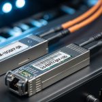
Think of an EN50155 optical module like a “weatherproof engine” rather than a consumer car battery. Standard SFP optics are designed around office or data center environments, while railway requirements target operational stability during rolling stock vibration, temperature extremes, and electrical transients. In practice, the key differences show up as expanded operating temperature, mechanical robustness, and tighter control of optical parameters over time. For trackside cabinets, that translates into fewer intermittent link drops and more predictable commissioning outcomes.
What EN50155 typically covers in optical modules
EN50155 is the railway standard that drives environmental qualification for equipment used on rolling stock and related infrastructure. For optics, the module vendor’s datasheet usually maps the standard to measurable limits: operating temperature range, power consumption stability, and reliability under vibration and shock. The optics themselves must also maintain performance under those conditions, meaning output power, receiver sensitivity, and eye safety remain within spec. Always confirm the exact qualification statement in the vendor datasheet, because not every “railway” label means the same test campaign.
Head-to-head: typical SFP optical families used on trackside
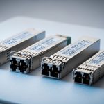
Most trackside SFP designs align to IEEE 802.3 physical-layer choices such as 1GBASE-SX, 1GBASE-LX, or 10GBASE-SR/LR depending on the backhaul architecture. The two most common fiber types are multimode for short runs and single-mode for longer reach and lower dispersion sensitivity. For trackside, single-mode is frequently preferred because it simplifies reach planning and tolerates smaller core variations over distance. However, multimode can still win when duct space is tight and the spans are short.

Performance comparison: wavelength, reach, and power budget for trackside links
When selecting an EN50155 optical module, the “best” choice is the one that closes your optical budget with margin while staying within temperature and power constraints. Engineers often start with wavelength and reach, but in rail deployments the real differentiator is how consistently the transceiver meets sensitivity across temperature. A module with marginal sensitivity at the cold end can pass in the lab and fail during winter commissioning. So the comparison must include both link budget and environmental limits.
Key optical parameters you should compare
Use the datasheet to compare wavelength (nm), nominal transmit power (dBm), receiver sensitivity (dBm), and supported fiber type. Then calculate the optical budget using your span loss, connector and splice loss, and any patch panel penalties. For safety, include a margin for aging and additional bends. Also check whether the module supports Digital Optical Monitoring (DOM) so you can trend laser bias current and received power in the field.
Technical specifications comparison table
| Parameter | Example 1GBASE-SX (Multimode) | Example 1GBASE-LX (Single-mode) | Example 10GBASE-LR (Single-mode) |
|---|---|---|---|
| Typical wavelength | 850 nm | 1310 nm | 1310 nm |
| Typical reach (nominal) | 300 m over OM3, up to 550 m over OM4 | 5–10 km typical | 10 km typical |
| Connector type | LC duplex | LC duplex | LC duplex |
| Tx power (range) | ~ -9 to 0 dBm (varies by vendor) | ~ -3 to 0 dBm (varies) | ~ -1 to 3 dBm (varies) |
| Rx sensitivity (typical) | ~ -17 to -19 dBm | ~ -20 dBm class | ~ -14 to -15.5 dBm class |
| Operating temperature range | Industrial: often -20 to +70 C | Rail-qualified options: often -40 to +85 C | Rail-qualified options: often -40 to +85 C |
| DOM support | Common on many SFPs | Common on many SFPs | Often available; depends on model |
| Railway standard fit | Only if explicitly EN50155 qualified | Only if explicitly EN50155 qualified | Only if explicitly EN50155 qualified |
Note: The values above illustrate typical ranges; always use the exact vendor datasheet for your chosen model.
Real deployment reality: optical budget isn’t just distance
In trackside cabinets, you often add splice trays, patch cords, and rework loops during commissioning. A 2 km run can quietly become a 2 km run plus four connectors and three fusion splices, each with a loss you must budget. Engineers commonly assume “fiber loss dominates,” but in the field, connector cleanliness and patch panel aging can become the limiting factor. That is why an EN50155 optical module should be treated as part of an end-to-end link budget, not a standalone part number.

Compatibility and switching: making SFP modules behave on real trackside switches
An EN50155 optical module can meet all optical specs and still fail operationally if it is not compatible with the switch’s SFP electrical requirements or its vendor firmware expectations. Many trackside designs use industrial Ethernet switches that support SFP/SFP+ cages with specific management behavior. The practical question becomes: will the link come up consistently at cold start, will DOM readouts work, and will the switch accept third-party optics without “unsupported transceiver” errors?
What to verify before purchase
- Data rate and interface standard: confirm the transceiver matches the port mode (for example 1G vs 10G).
- Connector and fiber type: LC duplex for most SFP optics; ensure OM3/OM4 vs single-mode fiber type matches the wavelength plan.
- DOM and management: check if the switch reads DOM safely and whether it flags alarms when values drift.
- Vendor compatibility: consult the switch vendor optics compatibility list when available.
- Power class and cage tolerance: ensure module power draw stays within the cage spec at low temperature.
Measured field behavior you should expect
In one common commissioning pattern, engineers observe that links come up warm but flap during cold soak. The root cause often is temperature-dependent laser bias behavior combined with slightly pessimistic optical budget assumptions. Another pattern is “DOM mismatch”: the switch accepts the link but logs transceiver warnings due to calibration differences. This is why you should validate with the exact switch model and optical patch hardware used on the site.
Cost and ROI: OEM vs third-party EN50155 optical modules
Cost is never just the unit price; it is also the commissioning time, spare interchangeability, and risk of incompatibility. OEM optics typically cost more but often reduce integration risk because the vendor has validated behavior with the same switch family. Third-party optics can be cheaper, yet you must budget time for compatibility tests and possibly accept higher failure variance across lots. For trackside, a single field swap may take hours due to access constraints, so ROI should include labor and downtime, not only the bill of materials.
Realistic price ranges and TCO thinking
Depending on speed and reach, optics often fall into ranges like: lower-cost industrial SFPs for short reach, mid-range qualified optics for single-mode, and higher-cost optics for 10G long-reach. In many projects, the total cost of ownership (TCO) is dominated by spares strategy, warranty terms, and the ability to hot-swap without reconfiguration. A practical approach is to standardize on one vendor and one DOM behavior model wherever possible to simplify monitoring dashboards and alarm thresholds.
Compatibility caveats to state upfront
Even when two optics claim the same standard data rate and wavelength, there can be differences in output power class, DOM scaling, and eye safety profiles. Some switches enforce “known optics” policies, which can block link establishment. Also, rail-qualified EN50155 claims must be verified against the specific module model number; a generic “industrial” label is not the same as an explicitly EN50155-qualified transceiver.
Pro Tip: In trackside acceptance tests, record DOM values (tx bias current, tx power, rx power) at both warm and cold conditions. If rx power is near the sensitivity edge, you will often see a predictable drift pattern before you ever experience a full link failure.
Selection criteria checklist for an EN50155 optical module on trackside
Use this ordered checklist the way you would in a procurement review meeting: quickly eliminate wrong options, then validate the survivors with field-realistic numbers.
- Distance and fiber plan: confirm span length, fiber type (OM3/OM4 vs single-mode), and connector/splice count.
- Optical budget closure: use vendor Tx/Rx specs and include a margin (commonly several dB) for aging and rework.
- Switch compatibility: verify port mode, DOM behavior, and whether the switch enforces transceiver allowlists.
- EN50155 qualification evidence: ensure the exact module model is listed as meeting the railway standard requirements.
- Operating temperature and power: confirm laser and receiver performance at the low-temperature end of your site.
- DOM support and monitoring: choose modules that expose stable metrics for alarms and trending.
- Vendor lock-in risk: decide whether you want one optics family for all sites or allow multiple vendors with a tested interchange plan.
Common mistakes and troubleshooting in trackside fiber SFP links
Even experienced teams can trip over a few predictable failure modes. Below are concrete pitfalls, likely root causes, and the fastest fixes you can apply during commissioning or after a service call.
Link flaps only during cold start
Root cause: optical budget is slightly short, and sensitivity margin collapses at cold temperature; laser output and receiver thresholds shift. Connector cleanliness may also worsen due to condensation cycles.
Solution: measure rx power with a calibrated optical power meter or use DOM trending, then add margin by adjusting patching, replacing high-loss connectors, or selecting a higher power-class module.
Switch reports “unsupported transceiver” or refuses to bring link up
Root cause: the switch firmware enforces compatibility rules, or the transceiver electrical characteristics do not match the cage requirements. Sometimes DOM signaling differs enough to trigger policy alarms.
Solution: confirm the exact module part number and DOM behavior supported by the switch vendor; if needed, test with the same switch model and run a controlled acceptance procedure before scaling.
High packet loss after maintenance, even though link is “up”
Root cause: fiber end-face contamination or micro-bending introduced during re-patching; the receiver may operate but with degraded optical signal quality.
Solution: clean connectors using approved fiber cleaning tools, inspect with a fiber microscope, then re-measure optical power and error counters. Replace patch cords if you see repeated contamination hotspots.
“Works on the bench” but fails after mounting in a cabinet
Root cause: thermal airflow differences change module temperature; enclosure heating raises internal temperature beyond assumptions. Vibration can also loosen patch hardware if strain relief is missing.
Solution: validate with the mounted enclosure thermal profile, add proper cable strain relief, and verify that the module’s specified operating temperature range covers your cabinet worst-case.
Decision matrix: pick the right EN50155 optical module option
Use this matrix to align technology choice with your constraints. The goal is to avoid “almost works” designs that only succeed under ideal lab conditions.
| Reader type / constraint | Best fit | Choose this when | Watch for |
|---|---|---|---|
| Trackside engineer optimizing reliability | EN50155-qualified single-mode SFP with DOM | You need longer reach and stable performance across temperature | Higher unit price; ensure switch compatibility |
| Budget-constrained project with short spans | EN50155-qualified multimode SFP (SX) | Runs are within OM3/OM4 reach limits with margin | Fiber type mismatch is a common risk |
| Operations team needing fast diagnostics | EN50155-qualified SFP with robust DOM support | You will trend rx power and alarms for proactive maintenance | DOM alarm thresholds differ by vendor |
| Large fleet rollout across many sites | Standardize on one vendor’s qualified module family | You want uniform spare parts and consistent monitoring | Vendor lock-in; mitigate with tested alternates |
Which option should you choose?
If you are deploying trackside links where temperature extremes and access constraints matter, choose an EN50155 optical module that is explicitly qualified for the standard, supports DOM, and matches your fiber type and switch port mode. If your spans are short and you have verified OM3/OM4 plant loss plus clean connectors, a qualified multimode SFP can be the cost-effective option. If you need consistent reach across uneven splice quality and longer backhaul, single-mode EN50155-qualified optics are usually the safer operational choice. For fleet-scale rollouts, standardize on one optics family and validate interchangeability with your exact switch models before you buy spares.
FAQ
What does EN50155 qualification mean for an optical module?
It means the vendor has qualified the module for railway environmental conditions aligned to EN50155 requirements, typically including temperature performance and robustness under vibration and shock. You must confirm the qualification statement for the exact module model number in the datasheet. Do not assume that any “industrial” SFP automatically meets EN50155.
Can I use a standard SFP in a trackside cabinet?
You might be able to make a standard SFP work in a controlled enclosure, but it is risky when you face cold starts, condensation, and vibration. Standard optics may not maintain receiver sensitivity across your worst-case temperature range. For railway acceptance, use explicitly qualified optics to reduce intermittent faults.
How do I calculate optical budget for an SFP trackside link?
Start with transmit power and receiver sensitivity from the module datasheet, then subtract expected fiber attenuation plus connector and splice losses. Include a margin for aging and maintenance rework. If you have DOM, use it during commissioning to confirm rx power sits comfortably above the sensitivity threshold.
Do I need DOM support for troubleshooting?
DOM is not strictly required for link establishment, but it can dramatically reduce mean time to repair by showing tx and rx levels over time. In the field, trending rx power helps you detect gradual contamination or aging before the link fails. If your switch supports DOM alarms, configure thresholds carefully based on your selected vendor’s scaling.
What switch compatibility checks matter most?
Confirm the port’s supported speed mode (1G vs 10G), connector type, and any transceiver allowlist behavior. Validate with the same switch model and firmware revision you will deploy, because optics acceptance policies can change. Test link bring-up and error counters at both warm and cold conditions when possible.
Are third-party EN50155 optical modules reliable enough?
They can be, but you must treat them like field-critical components: request datasheets with the exact EN50155 qualification for the model, verify DOM behavior, and run a compatibility test with your switch. For rail fleets, reliability is improved by standardizing on one tested vendor family and maintaining a structured spare strategy with warranty terms.
If you want to go one step further, pair this selection process with a link-monitoring plan that turns optical telemetry into maintenance actions. Next, review railway fiber monitoring and alarms to design practical thresholds and commissioning evidence for your trackside fleet.
Author bio: I have supported rail and industrial Ethernet deployments where field optics decisions determined commissioning success, including cold-start validation and DOM-based troubleshooting. I write with a field engineer mindset, focusing on measurable optical budgets, compatibility testing, and operational reliability.