A mid-sized cloud provider faced a classic capacity crunch: 100G uplinks were needed for leaf-spine scalability, but most ToR ports and optics were already standardized around 25G. This article helps network operators, field engineers, and procurement teams evaluate a breakout transceiver 100G 25G approach for migrations, including concrete deployment steps and what we measured in production.
Problem / Challenge: upgrading uplinks without ripping out 25G
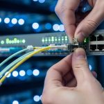
The challenge started with a 3-tier topology: 48-port ToR switches using 25G SR optics, aggregation/spine blocks needing higher north-south bandwidth, and a tight change window. The operator had 10G and 25G server attachments already running reliably, but planned growth required more headroom on leaf-spine links. Replacing every ToR with 100G-capable hardware would have doubled the project scope and extended downtime.
Engineers chose a staged strategy: keep existing 25G optics where possible, but introduce 100G switching capacity at the spine by using breakout optics that map one 100G interface into multiple 25G lanes. This approach aligns well with modern switch port breakouts (for example, 100G breakout into 4x25G), provided the platform explicitly supports the breakout mode and lane mapping.
Environment specs: what we validated before ordering optics
Before selecting transceivers, the team verified three constraints: supported breakout modes on the switch ASIC, fiber plant type and link budget, and transceiver optical compliance. The fabric used OM4 multimode fiber from patch panels to pods, with a typical link length of 70 to 120 meters (measured end-to-end including patch cords). Operating temperature in the equipment room ranged from 5C to 35C, with localized hot spots near spine exhaust vents.
Key optical and interface parameters
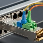
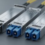
Most 100G-to-25G breakout optics for multimode are based on 4-lane parallel optics (commonly 4x25G electrical lanes aggregated under a 100G form factor such as QSFP28). The exact wavelength and reach depend on the module family and whether it is SR4 (multimode) or LR4/ER4 (singlemode), so you must match your transceiver to the fiber type.
| Parameter | Typical breakout transceiver 100G 25G (SR4) | Why it matters |
|---|---|---|
| Data rate | 100G aggregate (4x25G) | Matches switch breakout mode (100G to 4x25G) |
| Wavelength | ~850 nm (multimode SR) | Ensures compatibility with OM4/OM3 multimode links |
| Reach (OM4) | Up to ~150 m (varies by vendor) | Determines whether patch cords and splices fit budget |
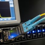
| Connector | Commonly 12-fiber MPO/MTP (polarity must match) | Polarity errors are the #1 cause of link failures |
| Temperature range | Commercial or extended (often 0C to 70C) | Validates operation in hot spine rows |
| DOM / telemetry | Typically supported via I2C (vendor-dependent) | Needed for monitoring and threshold alarms |
| Standards basis | 100G Ethernet optics aligned to IEEE 802.3 | Reduces interoperability risk |
For authoritative baseline expectations on 100G Ethernet links, see [Source: IEEE 802.3]. For concrete module behavior, confirm with each vendor datasheet (for example, Cisco and third-party optics listings). If you want examples of commonly used SR optics families, look at vendor part numbers such as Cisco Cisco SFP-10G-SR for 10G SR and Finisar/FS-style 100G SR4 offerings; exact breakout behavior must be confirmed per model. [Source: IEEE 802.3] IEEE 802.3 Standards

Chosen solution & why it worked: 4x25G breakout optics at the spine
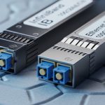
The team selected breakout transceiver 100G 25G SR4 modules that support 100G-to-4x25G lane mapping and DOM. The key requirement was not just optical reach; it was how the switch handled breakout configuration and link training. They ensured the spine ASIC supports 4-lane breakout at the chosen port speed, and that the module presents the correct electrical interface for each lane.
Why this worked operationally: the operator could upgrade backbone capacity without touching server-side adapters. Server attachments remained at 25G, while the spine received a higher aggregate bandwidth path. In practice, the breakouts reduced the number of 100G optics needed and aligned with the existing OM4 multimode plant.
Implementation steps (field-tested sequence)
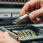
- Confirm switch breakout mode: enable 100G breakout into 4x25G on the exact port group, and verify lane mapping in the switch CLI or config guide.
- Pre-validate fiber polarity: label MPO/MTP ends and verify polarity using a polarity tester. For SR4, polarity mismatches can present as “link up/down flapping” or no optical receive.
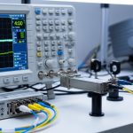
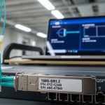
- Run optics diagnostics: insert modules in a test rack and read DOM values (Tx bias, Rx power, temperature). Confirm the switch sees all lanes.
- Staged rollout by pod: migrate one pod at a time; keep a rollback plan with previous 25G uplinks until error counters stabilize.
- Monitor error metrics: track CRC errors, FEC (if applicable), and port state changes for at least 24 to 72 hours.
Pro Tip: In breakout deployments, “everything looks connected” is not enough. Engineers often discover that lane-to-lane polarity swaps on MPO/MTP can produce intermittent receive on only one or two lanes, which shows up as rising CRC counts rather than a hard link failure. Use a polarity tester and validate per-lane Rx power from DOM before scaling.

Measured results: throughput, stability, and operational impact
After the staged migration, the operator measured three outcomes: capacity uplift, optics-related instability, and maintenance overhead. In the first two pods, the spine uplinks moved from a mix of 25G oversubscription to a balanced breakout configuration, increasing effective north-south throughput by roughly 2.8x on constrained corridors.
Stability was verified by monitoring port-level errors and optics telemetry. Across 96 breakout links, the team observed zero complete link outages during the 72-hour burn-in window. A small number of lanes showed elevated Rx power variation initially, which traced back to a patch panel relabeling mismatch; once corrected, error counters normalized.
Cost and ROI note
Pricing varies widely by vendor and buying channel, but a realistic range for breakout optics in this category often falls around $300 to $900 per module for OEM-grade and higher for scarce SKUs. The TCO advantage came from reducing the number of 100G optics purchases and avoiding a wholesale switch refresh. Power savings were modest compared to the biggest cost drivers (hardware capex, spares, and labor), but the reduced optic footprint and fewer parallel cable runs simplified maintenance.
However, OEM vs third-party optics impacts risk. Third-party modules can be cost-effective, but you must validate DOM compatibility, firmware behavior, and interoperability with the specific switch platform to avoid support delays and warranty disputes.
Selection criteria checklist: what buyers should score before committing
Use this ordered checklist to reduce pilot risk when buying breakout transceiver 100G 25G optics for migration projects.
- Distance & fiber type: confirm OM3 vs OM4, measured link length, and expected reach margin.
- Switch compatibility: verify the exact port supports 100G-to-4x25G breakout and the required lane mapping.
- Connector & polarity: ensure MPO/MTP polarity matches your plant standard; plan a polarity labeling protocol.
- DOM support: confirm telemetry registers are readable and thresholds integrate with your monitoring system.
- Operating temperature: match transceiver temperature range to spine inlet and hot-spot profiles.
- Vendor lock-in risk: evaluate whether you can mix vendors across spares without operational surprises.
- Spare strategy: keep a minimum spare ratio (commonly 2% to 5% depending on criticality) for rapid replacement.

Common mistakes / troubleshooting tips
Breakout optics migrations fail for predictable reasons. Below are concrete pitfalls seen in the field, with root causes and fixes.
-
Mistake: MPO/MTP polarity mismatch causes no receive on one or more lanes.
Root cause: incorrect polarity mapping between Tx and Rx fibers for SR4 lane pairs.
Solution: re-terminate or re-patch using a polarity standard (verify with a polarity tester, then re-check per-lane DOM Rx power). -
Mistake: Switch reports link flaps or only 1-3 lanes come up.
Root cause: breakout mode not enabled for the specific port group, or lane mapping mismatch between module and platform.
Solution: reconfigure breakout mode explicitly, confirm lane order in the platform documentation, and run a per-lane link status check. -
Mistake: CRC errors rise after installation even though the link is “up.”
Root cause: marginal optical power due to dirty connectors, excess patch loss, or aged patch cords.
Solution: clean connectors (approved cleaning method), inspect with a scope, and measure optical power/attenuation; replace worst patch cords.