In leaf-spine data centers and campus cores, a “mystery” link flap can cost hours before anyone proves whether optics, fiber, or optics settings are to blame. This article helps network and field engineers choose a DDM DOM optical transceiver by explaining how Digital Diagnostic Monitoring reports power, temperature, and bias currents, then mapping those signals to operational decisions. You will also get a practical spec comparison, a selection checklist, and troubleshooting steps that match what technicians see during live maintenance windows.
How DDM DOM optical transceivers expose laser and link health

Digital Diagnostic Monitoring (DDM) and its common DOM implementation let transceivers report internal parameters over the management interface. In practice, the module provides calibrated readings such as transmit power, receiver power, laser bias current, and module temperature. Many vendors also expose supply voltage and alarm thresholds that the host can poll.
At the Ethernet optics level, these behaviors align with the intent of the Small Form-factor Pluggable (SFP) and QSFP management frameworks and the operational expectations described in IEEE Ethernet optical link standards. For example, IEEE 802.3 defines optical link operation for Ethernet rates, while transceiver diagnostics are typically standardized through the transceiver management and serial ID mechanisms used by SFP/QSFP ecosystems. If you are validating behavior, start by correlating reported optics readings to link margin and BER trends.
What the host actually receives during monitoring
When DDM DOM is enabled, the host controller (switch ASIC, line-card management CPU, or an external monitoring system) reads diagnostic registers exposed by the optic. Typical alarms include “low/high transmit power,” “low/high receive power,” “high temperature,” and “high bias current.” In day-to-day operations, engineers use these values to detect failing optics before they cause packet loss.
Pro Tip: If receive power is slowly drifting while transmit power stays stable, suspect fiber contamination, connector wear, or an aging patch panel rather than a laser aging failure. Logging both curves over 24 to 72 hours usually separates “optics degradation” from “optical path loss” much faster than single-point checks.
Spec comparison: common DDM DOM optical transceiver types you will actually buy
Most procurement decisions start with form factor and speed, then narrow to wavelength and reach. DDM DOM availability is common across these categories, but the exact register set, alarm thresholds, and temperature range can differ by vendor and generation. Below is a representative comparison using widely deployed examples you can reference during RFP and spares planning.
| Optic example | Data rate | Wavelength | Reach | Connector | DDM DOM | Operating temp | Typical module power |
|---|---|---|---|---|---|---|---|
| Cisco SFP-10G-SR | 10G | 850 nm | ~300 m (OM3) | LC | Supported | 0 to 70 C (varies by exact SKU) | Low single-digit W |
| Finisar FTLX8571D3BCL | 10G | 850 nm | ~300 m (OM3) | LC | Supported | 0 to 70 C (typical) | Low single-digit W |
| FS.com SFP-10GSR-85 | 10G | 850 nm | ~300 m (OM3) | LC | Supported | 0 to 70 C (typical) | Low single-digit W |
| Generic QSFP+ 40G LR4 class | 40G | ~1310 nm | ~10 km class | LC | Supported | 0 to 70 C or wider options | Higher than SFP |
Note: exact reach depends on fiber grade (OM3 vs OM4), link budget, and host vendor calibration expectations. Always confirm the specific datasheet for your chosen SKU and ensure the module is compatible with your switch’s optics policy.
Real-world deployment scenario: using DOM to prevent avoidable downtime
Consider a 3-tier data center leaf-spine topology with 48-port 10G ToR switches feeding 16-port 100G spine uplinks. In one site, the team monitored DOM on 10G SR optics across six racks per row, totaling roughly 768 active links. Over two months, they observed that receive power for a subset of links dropped by 1.5 dB while temperature and bias current stayed within normal ranges. The root cause was a batch of patch panels where dust exposure increased during a ceiling work event.
Because the DDM DOM optical transceiver readings provided time-series visibility, the team scheduled a targeted cleaning and re-termination during a low-impact maintenance window. Instead of waiting for a full outage, they replaced only the affected jumpers and connectors. The operational win was measurable: fewer emergency calls, reduced mean time to repair, and improved predictability for future fiber maintenance.
Selection criteria checklist for DDM DOM optical transceiver procurement
When you buy optics, you are buying both physical performance and the management behavior your host expects. Use the checklist below to reduce returns, avoid surprise alarm thresholds, and protect your maintenance schedule.
- Distance and fiber grade: confirm OM3/OM4/OS2 category, connector type, and expected link budget margin under worst-case temperatures.
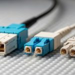
- Data rate and wavelength: match transceiver class to the switch port (10G SR, 25G SR, 40G SR4, 100G LR4, etc.).
- Switch compatibility and optics policy: verify whether your platform enforces vendor-specific transceiver checks or supports third-party optics.
- DOM/DDM support quality: confirm the module exposes the exact diagnostic fields your monitoring system reads, including alarm and threshold registers.
- Operating temperature range: pick “commercial” vs “industrial” class based on your environment, including intake air limits and hot-aisle conditions.
- DOM calibration behavior: ensure readings are stable and consistent across modules; validate with a burn-in and baseline logging.
- Vendor lock-in risk: weigh OEM spares availability versus third-party lead times, warranty terms, and return logistics.
- Supply chain resilience: check multiple sourcing options and confirm that the exact part number is stable (avoid “compatible” substitutions in production).
Cost and ROI: what DOM visibility is worth over the optic lifecycle
Pricing varies widely by vendor, form factor, and reach class. As a realistic planning range, many 10G SR optics for LC fiber commonly land in the low tens of dollars to low hundreds depending on whether you purchase OEM versus third-party and whether you include extended warranties. Higher-speed or longer-reach modules (such as 40G/100G LR4 class) can cost several hundred to over a thousand dollars each.
ROI comes from reduced downtime and reduced “truck rolls.” If DOM helps you catch failing optics or contaminated links earlier, you can lower the probability of emergency maintenance and shorten repair time. In total cost of ownership (TCO), also include labor for re-termination, connector cleaning supplies, and the risk of repeated failure due to misdiagnosis. Finally, remember that third-party modules can be cost-effective, but compatibility and DOM field completeness can vary by switch platform and firmware.
Common mistakes and troubleshooting tips for DDM DOM optical transceiver issues
Even when the optics are physically correct, field problems often come from diagnostics mismatches, fiber path issues, or host compatibility settings. Below are concrete failure modes you can use during incident response.
DOM shows “no alarms” while traffic still flaps
Root cause: the host may not be polling DOM correctly, or the monitoring system is reading different register mappings than expected. Some platforms also suppress alarms for certain transceiver types. Solution: confirm DOM polling is active in the switch CLI, validate the diagnostic registers your system reads, and cross-check with interface counters (CRC errors, FCS errors) and BER indicators if available.
Receive power is low, but transmit power and temperature look normal
Root cause: optical path loss from contamination, damaged connectors, or an incorrect fiber patch path. Bias current staying stable often points away from laser failure. Solution: clean both ends using proper fiber cleaning tools, inspect under magnification, verify patch cord polarity and path, and measure with an optical power meter or link test set if you have one.
Third-party optics are detected but DOM fields are incomplete or thresholds differ
Root cause: DOM/DDM implementation differences across vendors and firmware expectations on the host. Some monitoring dashboards assume a specific diagnostic layout. Solution: during acceptance testing, record baseline DOM outputs from a known-good OEM optic and compare register-by-register with the candidate module. If your monitoring system cannot adapt, standardize on a vendor family for that switch model.
“High temperature” alarms during normal operation
Root cause: airflow issues, blocked vents, or a module class mismatch for your environment. A module operating near its upper temperature limit can trigger alarms intermittently. Solution: verify switch cooling performance, check for obstructed intake/exhaust, confirm the module temperature spec for your SKU, and consider an industrial-temperature option.
FAQ
What does a DDM DOM optical transceiver report besides transmit power?
Most DOM implementations report laser bias current, module temperature, and receive power, often along with voltage and alarm threshold states. The exact set of fields depends on module generation and the host’s diagnostic interpretation. Always validate the field list against the module datasheet and your switch’s transceiver management documentation.
Do I need DDM DOM for reliable Ethernet, or is it just extra monitoring?
Reliable link operation does not strictly require DOM; optics can still pass traffic without active polling. However, DDM DOM becomes valuable for predictive maintenance, early detection of degradation, and faster root-cause analysis when interfaces show errors. In many operations teams, that reduces mean time to repair during incidents.
Will third-party DDM DOM optics work with OEM switches?
Often yes, but it is not guaranteed. Some platforms enforce compatibility checks or exhibit differences in how they interpret DOM registers and thresholds. The safest approach is to validate the exact part number on the exact switch model and firmware before scaling purchases.
How can I use DOM readings to estimate link margin?
Start by capturing a baseline at commissioning, then track how receive power changes over time. Combine DOM receive power with your fiber attenuation assumptions and verify against the expected receiver sensitivity for your optics class. For formal qualification, use a link budget methodology and confirm with a test plan aligned to your internal standards.
What should I log for an optics failure investigation?
Capture the time series of transmit power, receive power, bias current, and temperature around the incident window. Also record interface error counters and any DOM alarm events. This helps distinguish fiber contamination, connector damage, and optics aging quickly.
Where can I verify the diagnostic expectations for my transceiver class?
Use the vendor datasheet for the specific transceiver SKU and the switch vendor documentation for diagnostics and optics support. For Ethernet optical requirements at the link layer, reference IEEE 802.3 related optical PHY clauses. Authority sources are also helpful for understanding transceiver management concepts: IEEE Standards.
DDM DOM optical transceivers turn “unknown optics health” into measurable signals that your team can act on before downtime spreads. If you are standardizing across racks, run a short acceptance test, baseline DOM readings, and then scale procurement using the compatibility checklist. For related planning, see fiber link budget and optical reach planning.
Author bio: I have deployed and troubleshot DOM-enabled SFP and QSFP optics in multi-vendor data centers, including live DOM baseline logging and connector contamination remediation. I focus on procurement decisions that balance spec match, lead time, compatibility risk, and operational reliability.
Update date: 2026-04-27