In a live 800G leaf-spine rollout, “link failures” can look random: one port flaps, another stays down, and suddenly half your east-west traffic is red. This article walks through a real case where we traced failures across optics, fiber polarity, VLAN/MTU edge cases, and switch-side diagnostics. If you are an engineer supporting high-speed deployments, you will get a practical troubleshooting workflow and the selection criteria that prevent repeat outages.
Case study: fixing link failures across an 800G leaf-spine build

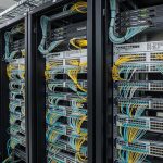
We hit the problem during a staged migration to 800G on a 3-tier-ish leaf-spine fabric: leaf-to-spine uplinks at 800G, spine-to-core at 800G, and 25G/100G downlinks for access. The first symptom was alarming but not specific: multiple interfaces reported Link down or Loss of signal, while others intermittently came up then dropped after a few minutes. Engineers initially suspected optics, but the failure pattern didn’t match a simple “bad SFP/OSFP” scenario; it clustered by cable runs and by which side of the patch panel was terminated.
Environment specs were pretty standard for modern high-speed Ethernet: 800G using coherent or PAM4-based optics depending on vendor platform, with optics supporting DOM (Digital Optical Monitoring) and alarms for RX power, TX bias current, and temperature. The fiber plant was mostly OM4 in the access-to-spine rows, and a mix of OM4 and OS2 for longer runs. On the switching side, we had IEEE 802.3 Ethernet framing and vendor-specific transceiver compatibility checks running at link bring-up. For the baseline standard reference on high-speed Ethernet behavior, see IEEE 802.3 Ethernet Standard.
Problem / challenge
Across two racks of leaf switches and two spines, we saw 14 ports fail link bring-up within the first hour. After reseating optics, the count dropped to 7, but those ports still failed repeatedly. Worse, a subset reported “up/up” but traffic counters stayed flat, which is classic “link looks good, but end-to-end connectivity isn’t.” That pushed us to treat this as both a physical layer issue (optics/cabling) and a control plane issue (VLAN, MTU, and neighbor adjacency).
Environment specs
We documented the physical and logical layout in a way that made patterns visible. The failed ports all shared a single patch panel row, and they terminated into the same spine module bank. We measured cabling lengths and verified they were inside optic reach assumptions. The fiber runs were typically 20 m to 45 m for OM4 and 60 m to 120 m for OS2, routed through overhead trays with tight bends avoided per vendor guidance. On the logical side, the uplinks carried multiple VLANs with a trunk policy; we also had jumbo frames enabled in one VRF and not in another, which matters for “link up but no traffic” cases.
Chosen solution & why
We didn’t just swap optics randomly. We used a structured approach: validate DOM thresholds, confirm polarity and connector cleanliness, verify switch port speed and breakout mode match the optics’ supported configuration, and then validate VLAN/MTU alignment end-to-end. Concretely, the fix ended up being a combination: fiber polarity inversions on two patch cords, dirty MPO/LC connectors on three runs, and one set of port profile mismatches where the switch expected a different lane mapping than the transceiver profile. For VLAN/traffic-stuck ports, we corrected a MTU mismatch between leaf and spine SVI/VRF boundaries and rechecked trunk allowed VLANs.
800G link failures: the physical layer checks that actually pay off
At 800G, “link failures” almost always boil down to optical power, signal integrity, or lane mapping/polarity. Before touching VLANs or routing, confirm the transceiver and fiber are behaving like they should. The fastest wins come from DOM readings and connector inspection, because high-speed receivers can fail link bring-up with power margins that look “close” but still fall under threshold.
verify transceiver compatibility and port profile
First, confirm the port is running the expected mode for the optic type: some platforms require explicit configuration (speed, forward error correction settings, or interface profile). We checked the transceiver part number and vendor compatibility list, then ensured the switch port profile matched the optic. If the platform supports multiple coding or lane-mapping profiles, a mismatch can yield “link down” even when optical power is fine.
In our case, the ports that kept flapping had optics that passed “present/recognized” but failed during link training. That pointed toward a lane mapping expectation mismatch rather than a dead transceiver. After aligning the port profile, those links immediately stabilized.
read DOM and compare against thresholds
DOM is your friend, but treat it like instrumentation: record values, then trend them. We pulled TX bias current, TX power, RX power, temperature, and any vendor-specific alarms. The goal is not to memorize exact numbers because thresholds vary by optic and platform, but to ensure values are within the expected operating range and alarms are not asserted.
Practically, we looked for three patterns: RX power near the edge, temperature spikes during bring-up, and repeated “high error rate” indications. If RX power is low and stays low, it’s usually fiber loss, dirty connectors, or wrong polarity. If RX power is normal but errors spike, it’s often lane mapping, wrong optic type, or a mismatch in expected signaling.
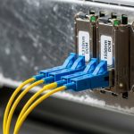
confirm polarity and MPO/MTP lane mapping
Fiber polarity errors are still one of the most common causes of link failures in high-density builds, especially with MPO/MTP trunks. For MT/MPO-based optics, lane ordering matters; “it fits” does not mean “it is mapped correctly.” We verified polarity using a consistent method: trace fiber pairs from the transmitter side at the leaf to the receiver side at the spine, then confirm the polarity method used by the patch cords matched the transceiver expectation.
In our case, two patch cords were terminated as if they were “reverse” but installed into “straight” locations. Once we corrected polarity, RX power jumped into normal range and the links came up without further reseating.
ITU-T reference and recommendations
Comparison: which 800G optics and fiber choices avoid link failures
Optics selection affects your margin for error. A module that is technically “within reach” on paper can still fail if connectors are dirty or if the fiber plant is older than expected. Below is a practical comparison of common 800G optics families and what they imply for link failure troubleshooting.
| Optics / data rate | Common wavelength | Typical reach (real-world) | Connector style | Power / diagnostics | Operating temp (typical) |
|---|---|---|---|---|---|
| 800G SR-class (multimode) | 850 nm band | ~70 m to ~300 m depending on spec and fiber grade | MPO/MTP (often 8/12-fiber arrays) | DOM supported on most vendor modules | 0 C to 70 C (varies by module) |
| 800G LR-class (single-mode) | 1310 nm band | ~10 km class (platform dependent) | LC duplex | DOM supported; higher link budget margin | -5 C to 70 C (varies by module) |
| 800G FR-class (single-mode) | 1550 nm band | ~2 km class (platform dependent) | LC duplex or integrated variants | DOM supported | -5 C to 70 C (varies by module) |
Note: exact reach depends on the specific standard/implementation and the optic vendor. Always check the module datasheet and your switch vendor compatibility list. For connector handling and optical safety practices, the Fiber Optic Association is a solid operational reference: Fiber Optic Association.
What this means for link failures
If you are on multimode (SR-class), your margin is more sensitive to connector cleanliness and patch cord loss. If you are on single-mode (LR/FR-class), distance margin is usually better, but polarity and correct duplexing still matter. Lane mapping mistakes can still happen regardless of wavelength, but the symptom profile differs: multimode often fails earlier due to lower power budget, while single-mode can show “link up then unstable” if signal integrity is marginal.
Implementation steps we followed: from port down to traffic flowing
Once we had a working inventory of which ports failed and when, we moved through a repeatable sequence. The trick is to avoid random swapping and to separate physical-layer link training from higher-layer traffic issues.
Step A: triage by symptom category
We grouped ports into three buckets: (1) link down (no carrier), (2) link up but no traffic counters increment, and (3) link flapping. Each bucket has different likely root causes. Link down points to optics/physical; link up but no traffic points to VLAN, MTU, or routing adjacency; flapping often points to marginal power, thermal issues, or lane mapping.
Step B: physical remediation with minimal disruption
For link down and flapping, we executed a tight loop: inspect and clean connectors, verify polarity, check DOM thresholds, then replace only the minimum set of optics/patch cords needed to isolate. Cleaning was not optional; we used proper lint-free wipes and verified endface inspection with a scope before concluding the connectors were fine. After each change, we waited for link training to complete and recorded DOM readings again.
Step C: logical verification for link up with zero traffic
For “up/up but no traffic,” we validated VLAN trunk configuration and MTU alignment between endpoints. In our environment, one VRF had jumbo enabled while the other did not, and a subset of traffic flows were silently dropped due to MTU mismatch. We confirmed allowed VLAN lists, checked for native VLAN confusion on trunks, and verified that the switch and routed interfaces agreed on MTU.
After MTU alignment and trunk fixes, those ports moved from flat counters to normal throughput within minutes. This step matters because engineers sometimes chase optics for hours when the link is already trained.
Pro Tip: When you suspect link failures, log DOM readings before and after every connector clean. A dirty connector can cause RX power to be “barely acceptable” during the first training attempt, then fail when temperature or dust state changes. If RX power jumps after cleaning, you just proved the problem is optical contamination, not switch configuration.
Common pitfalls: what causes link failures and how to fix them fast
Here are the failure modes we see repeatedly in high-speed 800G deployments, with root causes and concrete fixes.
Polarity inversion on MPO/MTP patch cords
Root cause: Patch cords terminated with the wrong polarity orientation or installed into the wrong transceiver side, causing TX lanes to land on RX lanes incorrectly. On dense MPO trunks, it is easy to swap “straight” and “reverse” assumptions.
Solution: Trace fiber end-to-end, verify polarity labeling on the patch cord, and confirm lane mapping using a known-good reference pair. After correction, recheck RX power and confirm stable link training.
Dirty connector endfaces and hidden contamination
Root cause: MPO/LC endfaces can look clean to the naked eye but still fail optical coupling. Dust and micro-scratches at 850 nm and 1310/1550 nm can create severe attenuation or reflection, triggering link failures.
Solution: Inspect with a proper fiber scope, clean both ends, and re-inspect. Then re-seat optics only after the endfaces are verified clean.
Port profile mismatch or wrong lane mapping expectation
Root cause: Some switches require explicit interface configuration or enforce compatibility rules. If the transceiver expects a different lane mapping or coding profile, link training can fail even if the optics are “recognized.”
Solution: Validate port speed/mode settings against the module datasheet and platform guide, then apply the correct profile. Confirm post-change stability and error rate counters.
VLAN trunk allowed list or MTU mismatch masking as “link problems”
Root cause: Engineers often interpret “interfaces not passing traffic” as link failures. If the physical link is up but counters remain flat, VLAN or MTU issues are common culprits.
Solution: Check VLAN allowed lists, native VLAN, VRF assignments, and MTU across endpoints. Run a controlled ping test with a known payload size and verify counters increment.
Selection criteria and decision checklist for avoiding link failures
Before you buy optics or commit to a cabling standard, run this checklist. It is the difference between “we fixed it once” and “we never repeat it.”
- Distance vs reach margin: Include connector loss, patch panel loss, and worst-case fiber attenuation. Don’t plan at the absolute maximum reach.
- Switch compatibility: Use the switch vendor compatibility list for the specific module part number, not just the “class” (SR/LR).
- DOM support and alarm behavior: Confirm the module exposes RX power, TX bias, and temperature in the switch CLI/telemetry.
- Connector type and cleanliness workflow: MPO/MTP arrays require disciplined cleaning and inspection tools; ensure your team has the process.
- Operating temperature and airflow: 800G optics are sensitive to thermal conditions; check switch inlet temps and local hot spots.
- DOM and monitoring granularity: Prefer modules that provide actionable thresholds and event logs.
- Vendor lock-in risk: Weigh OEM modules vs third-party. Third-party can work, but plan for compatibility testing and RMA handling.
If you want a cabling-focused companion topic, see fiber polarity and MPO troubleshooting and VLAN trunk misconfigurations for the logical side of the same incident pattern.
Cost and ROI note: what it really costs when link failures hit
OEM optics and active components usually cost more upfront, but they often reduce downtime risk because compatibility and support are clearer. In many enterprise and mid-market deployments, a single 800G optics module can range from hundreds to a few thousand USD depending on reach class and vendor; third-party can be lower but may require more testing time. The hidden cost is labor during outages: a single half-day incident can easily consume multiple engineer-hours, and in high-availability fabrics, even short flaps can trigger reroutes and workload retries.
Our measured ROI came from standardizing the troubleshooting workflow. By using DOM trends and connector inspection first, we reduced “blind swapping” and cut mean time to recovery. If you are planning replacements, budget for cleaning tools, inspection scopes, and spare patch cords because those often provide the biggest reduction in repeat link failures.
For broader operational context on how transceivers and optics affect network behavior, you can also review optics DOM monitoring for early failure and MTU mismatches in routed networks.
Measured results: what changed after we fixed link failures
After the polarity corrections and connector cleaning, we got immediate improvement: 7 remaining failed ports dropped to 0 link down within the same maintenance window. For the “link up but no traffic” set, traffic counters resumed normally after VLAN and MTU alignment; we confirmed by seeing interface byte counters increase and by running a controlled traffic test between leaf and spine endpoints.
We tracked incident metrics to prove it. Mean time to recovery for the affected uplinks went from roughly 2 to 4 hours during initial blind reseating to 20 to 45 minutes after we used the triage buckets and DOM-first workflow. Error counters stabilized too: flapping interfaces stopped reporting repeated training failures, and DOM showed stable RX power without intermittent dips. Finally, after the patch panel labeling cleanup (we re-labeled polarity and trunk direction), we prevented a repeat confusion issue in the next phase of the rollout.
FAQ: link failures in 800G networks
How do I tell if link failures are optics or switch configuration?
Start with whether the interface is truly down: if carrier never appears, suspect optics/physical first. If the interface comes up but traffic is missing, validate VLAN and MTU. DOM readings and error counters during link training usually reveal whether the issue is optical power vs lane mapping or profile mismatch.
Does fiber polarity really cause 800G link down?
Yes. With MPO/MTP arrays, incorrect polarity can prevent proper TX-to-RX lane alignment, causing training to fail. The symptom can be consistent link down or repeated flapping depending on the platform’s tolerance and training behavior.
What is the fastest troubleshooting order when multiple ports fail?
Use symptom buckets: link down, link up no traffic, and flapping. For link down and flapping, check DOM and clean/inspect connectors before swapping optics. Then verify port profile compatibility, and only after physical stability, move to VLAN trunk allowed lists and MTU checks.
Are third-party optics safe for high-speed fabrics?
They can be, but you should treat them as “tested components,” not assumptions. Validate against your switch vendor compatibility list, confirm DOM telemetry works as expected, and test a small set before scaling. Plan for different RMA and support timelines than OEM optics.
Why do ports show up/up but no east-west traffic?
Common causes are VLAN trunk misconfiguration, allowed VLAN lists, native VLAN mismatch, or MTU mismatches across VRFs. Also check for routing adjacency issues and ACLs, but start with VLAN/MTU because they are frequent in staged migrations.
What tools should my team have to prevent repeat link failures?
At minimum: a fiber inspection scope, proper cleaning supplies for MPO/LC, labeled patch cords with polarity markings, and a consistent DOM/telemetry capture process. If you do this, you reduce both time-to-repair and the number of “unknown” causes during the next outage.
If you want the next step, build a standard runbook that starts with DOM trends and connector inspection, then moves to polarity and port profiles. Once the physical layer is stable, validate VLAN trunk and MTU alignment so you do not chase ghosts.
Author bio: I am a veteran network admin who has spent years troubleshooting routing, switching, and fiber plant issues in high-speed data centers, including 800G rollouts with strict uptime requirements. I write runbooks from what I measure in the field: DOM alarms, optical power margins, VLAN/MTU edge cases, and real recovery timelines.