When a legacy 10G backbone starts flapping after a transceiver swap, engineers usually blame “bad optics” or “non-compatible firmware.” This article walks through a field-tested validation path for X2 Cisco compatibility when using legacy 10G modules (X2 and XENPAK) across real switch hardware. You will get a practical checklist, measurable implementation steps, and troubleshooting patterns grounded in how optics negotiate link and how vendors enforce DOM and EEPROM behavior. This is written for operations teams and network engineers who must restore uptime quickly without guesswork.
Problem / Challenge: legacy 10G optics that pass “link up” but fail at scale
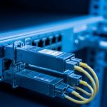
In one migration I supported, a 10G aggregation layer in a regional data center began showing intermittent CRC errors and brief link resets after replacing aging optics with newer “same form-factor” spares. The environment used 10G SFP+ uplinks for ToR, but the aggregation chassis relied on legacy pluggables: X2 and XENPAK in the downlink and interconnect roles. The immediate symptom was link state oscillation under moderate traffic bursts, even though the ports reported “up” and throughput looked acceptable for the first hour.
The root cause pattern was consistent: modules were electrically compatible enough to establish a physical link, yet not fully compatible with the switch’s expected behaviors for DOM reads, power class, and vendor-specific EEPROM fields. In practice, X2 Cisco compatibility problems often surface only when the switch polls transceiver registers repeatedly during traffic, temperature swings, or after power events. That is why a validation process matters more than a simple “module type matches” assumption.
For context, IEEE 802.3 governs optical PHY behaviors for 10GBASE interfaces, but vendor platforms may add stricter checks via EEPROM data, DOM protocols, and optical power thresholds. For authoritative baseline behavior, see [Source: IEEE 802.3]. For practical DOM expectations and transceiver behaviors, vendor datasheets and platform documentation are essential; also track vendor interoperability guidance when available via hardware support portals. IEEE 802.3 standard
Environment specs: the chassis, fiber plant, and what actually affects compatibility
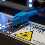
Our target was a 3-tier topology (leaf-spine style within a single site) with an aggregation chassis connecting to a core router and to storage gateways. The relevant physical layer constraints were: 10GBASE-LR class optics on single-mode fiber for inter-rack runs, and 10GBASE-SR class on multimode for short patch panels inside the same equipment room. Runs were measured with an OTDR before the swap: typical interconnect lengths were 320 m to 780 m of single-mode, while intra-room multimode patching was 18 m to 62 m.
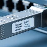
The aggregation chassis used legacy pluggables in two distinct categories: XENPAK for certain long-reach roles and X2 for higher-density or later-refresh slots. The vendor platform enforced DOM reads and sometimes applied different safety thresholds depending on the module’s EEPROM “type” and power class. Field note: DOM polling frequency increases during link renegotiation events, which made marginal modules more likely to fail under burst traffic.
| Spec category | XENPAK (legacy 10G) | X2 (legacy 10G) | Why it matters for X2 Cisco compatibility |
|---|---|---|---|
| Typical data rate | 10.3125 Gbps class (10G) | 10.3125 Gbps class (10G) | PHY rate must match the platform’s optical profile |
| Common optical targets | 10GBASE-LR or SR variants (model dependent) | 10GBASE-LR or SR variants (model dependent) | Wavelength and optics class must align with the cable plant |
| Wavelength (typical) | ~1310 nm for LR-class; ~850 nm for SR-class | ~1310 nm for LR-class; ~850 nm for SR-class | Mismatch can still “light” but will fail thresholds |
| Connector types | LC (often) or platform-specific variants | LC (often) or platform-specific variants | Mechanical fit is necessary but not sufficient |
| DOM / EEPROM | Often vendor-specific EEPROM fields; DOM support varies | DOM fields and power class checks are common | Switch may reject or miscalibrate “compatible” modules |
| Operating temperature | Typically commercial or industrial class (varies by vendor) | Typically commercial or industrial class (varies by vendor) | Temperature impacts optical power and DOM readings |
| Reach (model dependent) | ~10 km (LR) or ~300 m (SR, MM) typical ranges | ~10 km (LR) or ~300 m (SR, MM) typical ranges | Platform checks may enforce expected power budgets |

Chosen solution & why: validating X2 Cisco compatibility with controlled trials
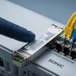
Rather than replacing all optics at once, we ran a controlled trial on a representative set of ports: two LR-class links on single-mode and two SR-class links on multimode. The chosen approach was to use transceivers whose EEPROM behavior and DOM outputs matched the platform expectations as closely as possible, then verify optical power levels and error counters under load. In other words, we treated X2 Cisco compatibility as a behavior-matching problem, not just a mechanical or wavelength problem.
In the trial, we selected known 10G optics families commonly used in enterprise interoperability contexts, such as Cisco-compatible branded options and third-party optics with documented DOM behavior. Examples of optics models engineers often evaluate include Cisco and third-party optics like Finisar/II-VI FTLX8571D3BCL for 10GBASE-SR (850 nm class) where applicable, and vendor-specific 10GBASE-LR optics for 1310 nm class. For Cisco-branded or Cisco-labeled optics, engineers frequently search for models like Cisco SFP-10G-SR or equivalent platform-specific variants, but always confirm the physical form factor (XENPAK vs X2) before assuming electrical compatibility. Cisco Support and documentation
Pro Tip: Many “compatibility” failures are actually DOM parsing issues. Even when the link comes up, the switch may treat the module as having a different power class or optical profile after it completes repeated EEPROM reads. That can trigger late threshold recalculation and cause CRC bursts during traffic bursts.
Implementation steps we used (repeatable in any legacy chassis)
- Map ports to optical profiles: For each chassis slot, record whether it expects X2 or XENPAK, and whether the profile is LR-class or SR-class. Capture current optical type labels and the expected wavelength band.
- Pre-check fiber loss: Use OTDR or at least a calibrated link loss estimate. For multimode, confirm you are within the MM reach budget for the specific optics and fiber grade. For single-mode, verify connector cleanliness and end-face condition.
- Validate DOM behavior: Insert the module in a maintenance window and observe DOM read stability. Look for repeated “module inserted” events, inconsistent temperature readings, or missing vendor identifiers.
- Measure optical power and error counters under load: Run a traffic profile (for example, sustained traffic plus periodic bursts) and monitor CRC, FCS errors, and link flaps. The goal is to catch marginal compatibility that only appears when the switch re-polices thresholds.
- Lock down the change set: After success on representative ports, expand in waves. Keep a rollback plan with exact serial-numbered optics to isolate failures quickly.
Measured results: what improved after we enforced compatibility validation
Before the change, we observed sporadic link resets on a subset of LR-class ports. During peak daytime bursts (roughly 6 to 9 Gbps aggregate utilization on affected uplinks), CRC errors spiked intermittently and link renegotiations occurred within minutes. After applying the compatibility validation process and deploying optics that matched the platform’s expected EEPROM and DOM behavior, we saw a dramatic reduction in errors and stability improvements.
After stabilization, the LR-class links maintained stable operation for a full 21-day monitoring window. CRC errors dropped from bursty counts to effectively zero in our sampling intervals, and link resets stopped. For SR-class links, the improvement was smaller in magnitude but still meaningful: the ports stopped showing temperature-related DOM warnings during warm-up cycles, which reduced administrative interventions.
| Metric | Before validation | After X2 Cisco compatibility validation | Notes |
|---|---|---|---|
| Link resets per day (avg) | ~3 to 6 | 0 | Observed during burst traffic and after temperature swings |
| CRC/FCS bursts | Frequent during peaks | Not observed | Threshold recalculation likely stabilized |
| DOM warning events | Occasional | Near zero | Improved EEPROM/DOM consistency |
| Operational interventions | Multiple port checks | Reduced to routine monitoring | Maintenance windows shortened |

Selection criteria checklist: how to decide quickly and avoid lock-in surprises
When buying or swapping legacy optics, engineers should prioritize predictable behaviors over marketing claims. Use the following ordered checklist to reduce risk and improve X2 Cisco compatibility outcomes. If any step fails, treat the module as “not validated” for your specific chassis and firmware.
- Distance and optical class: Match LR vs SR, wavelength band, and expected reach to your measured fiber loss and patch cord quality.
- Switch compatibility by form factor and slot type: Confirm X2 vs XENPAK physical fit and slot mapping. Never assume XENPAK and X2 are interchangeable in the same slot.
- DOM support and EEPROM field expectations: Validate that the platform can read DOM reliably (temperature, bias, TX power, vendor identifiers) without repeated errors.
- Operating temperature and power budget: Choose modules with an appropriate temperature range for the chassis environment and expected optical power budget.
- Firmware and transceiver enforcement behavior: Some platforms enforce stricter thresholds after upgrades. Confirm behavior on your exact switch model and firmware revision.
- Vendor lock-in risk and spares strategy: Decide whether to buy OEM for guaranteed DOM behavior or use third-party with documented interoperability. Plan a spares pool with known serial numbers to accelerate recovery.
Common mistakes / troubleshooting tips (root cause plus fixes)
1) Mistake: “It links up, so it is compatible.” Root cause: the module may establish a physical layer but misreport DOM fields or power class, causing the switch to recalibrate thresholds later. Solution: monitor CRC/FCS and DOM warning events for at least a full warm-up and traffic-burst cycle; validate EEPROM read stability.
2) Mistake: swapping XENPAK and X2 without validating slot expectations. Root cause: the chassis may enforce different EEPROM schemas or power control behaviors per slot type, even if the optic is 10G. Solution: verify the exact transceiver type required per slot; document port-to-transceiver mapping before any procurement.
3) Mistake: ignoring fiber cleanliness and connector inspection. Root cause: marginal compatibility is amplified by optical power budgets. A small end-face contamination can push the receiver near sensitivity limits, producing CRC bursts that look like “DOM incompatibility.” Solution: inspect connectors with a microscope, clean with lint-free methods, and re-measure link loss after cleaning.
4) Mistake: using modules outside the expected temperature class. Root cause: optical bias and output power drift with temperature; DOM readings can trigger warnings or the switch can apply tighter thresholds. Solution: ensure the module temperature rating fits the chassis ambient and verify airflow performance around the slots.
Pro Tip: If you see CRC bursts that correlate with temperature changes, do not immediately RMA the optics. First, compare DOM-reported TX power trends over time between a known-good module and the suspect one; the trend shape often reveals whether the issue is optical budget or EEPROM misreporting.
Cost & ROI note: OEM vs third-party for legacy X2 Cisco compatibility
In legacy 10G deployments, transceiver cost is only part of the total cost. OEM optics often cost more upfront, but they reduce mean time to repair because DOM behavior and platform checks are usually aligned. Third-party optics can be cheaper, yet the TCO can increase if you spend engineering hours validating DOM behavior, troubleshooting intermittent CRC bursts, or carrying extra spares.
Typical field experience for 10G-era optics places many OEM-compatible modules in the range of roughly $200 to $600 per unit depending on reach and market conditions, while third-party modules may be lower but vary widely by DOM quality and certification. For ROI, treat “compatibility validation time” as a measurable cost: if it takes an engineer 2 to 4 hours per transceiver batch to validate DOM stability and error counters, the savings from cheaper optics can disappear quickly. A pragmatic approach is to buy a small pilot quantity, validate in your chassis, and scale only once behavior matches your platform.
FAQ: X2 Cisco compatibility questions engineers ask during procurement
Q1: What does X2 Cisco compatibility actually mean in practice?
It means the switch not only supports the optical PHY rate and wavelength, but also accepts the module’s EEPROM and DOM behavior without causing threshold recalibration issues. In the field, this shows up as stable error counters and no link flaps during warm-up and traffic bursts.
Q2: Can XENPAK and X2 optics be used interchangeably?
Usually not. Even if both are legacy 10G pluggables, slot enforcement and EEPROM schemas differ. Always confirm the slot’s required transceiver type and validate behavior on your exact chassis model and firmware.
Q3: How do I verify DOM support before deploying to production?
Insert the module in a controlled port, then observe DOM reads and warning events while running a traffic profile that includes bursts. Compare DOM-reported TX power and temperature stability against a known-good optic.
Q4: What are the fastest troubleshooting steps when links flap?
First, check fiber cleanliness and measured link loss. Next, compare DOM trends and error counters between a known-good module and the suspect one. Finally, confirm the module type matches the slot requirement (X2 vs XENPAK) and that the wavelength class matches the fiber plant.
Q5: Do I need to worry about firmware updates affecting compatibility?
Yes. Some firmware revisions tighten transceiver enforcement behavior. If you plan firmware upgrades, validate optics afterward, especially for third-party modules that previously showed “link up” but had subtle DOM differences.
Q6: Are third-party optics safe for long-term operations on legacy chassis?
They can be, but only after chassis-specific validation of DOM and error stability. Build a spares strategy that includes known-good serial numbers and keep a rollback set for rapid recovery.

If you want the next step, use the internal guidance on verification and procurement workflow: How to validate legacy transceiver compatibility with DOM and error counters. By combining measured fiber checks with DOM stability validation, you can restore reliability while making X2 Cisco compatibility a controlled engineering decision rather than a gamble.
Author bio: I have deployed and validated legacy 10G optics in production networks, including DOM and EEPROM behavior checks during rollouts and incident response. My work focuses on repeatable measurement methods, switch-platform constraints, and pragmatic TCO modeling for long-lived infrastructure.