If your 10G or 100G links keep flapping, the root cause is often not the fiber or the switch, but the optical transceiver brand and its module behavior under real temperature and power conditions. This article helps network engineers and field techs do a practical transceiver brand comparison focused on quality, reliability, and price, using the same kinds of checks you would run in a lab and then validate in production. You will get a spec table, a concrete data center scenario, a decision checklist, and troubleshooting patterns that match common failure modes.
Why transceiver brand comparison matters in real networks
Optical transceivers are not interchangeable “black boxes.” Even when two brands both claim compliance with IEEE 802.3 and the same form factor (SFP+, QSFP+, QSFP28, or OSFP), the internal transmitter biasing, receiver sensitivity, and DOM implementation details can differ. In practice, those differences show up as higher BER under marginal optics, unexpected link training delays, or incompatibility with switch vendor telemetry expectations. When you compare brands, you are comparing the full system behavior: optics, firmware, DOM, and thermal margins.
For reference, the Ethernet physical layer expectations come from IEEE 802.3 (for example, 10GBASE-SR, 40GBASE-SR4, 100GBASE-SR4). The exact optical performance targets are defined by the standard, but vendor implementation still affects how consistently a module stays within spec across temperature swings and aging. For module types, also check the relevant SFF specifications for the electrical/DOM interface (for example, SFF-8472 for SFP/SFP+ optical modules, and QSFP+ / QSFP28 management references where applicable) and the vendor datasheet for absolute maximum ratings.

Specs that actually drive reliability: what to compare
Most procurement sheets stop at wavelength and “reach.” Reliability is usually decided by how a module performs at the edges: high ambient temperature, worst-case link budget, and operating power limits. In a transceiver brand comparison, you should capture the module’s electrical interface class, optical parameters, and DOM feature set, then validate them against your switch optics behavior.
Key optical and system specifications to record
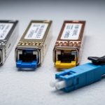
- Wavelength (e.g., 850 nm for SR, 1310/1550 nm for LR/ER)
- Data rate and lane structure (10G, 25G, 40G SR4, 100G SR4)
- Reach target (meters for OM3/OM4 with typical assumptions)
- Connector (LC, MPO/MTP)
- Temperature range (Commercial vs Industrial grade)
- Optical power and receiver sensitivity (vendor datasheet values)
- DOM support (diagnostic registers availability and threshold behavior)
- Compliance notes (EEPROM layout, speed ID, and any vendor-specific caveats)
Comparison table: common 10G SR and 100G SR4 module targets
This table is a practical baseline. Actual numbers vary by vendor and exact part number, so treat it as a template for your own transceiver brand comparison, not a guarantee.
| Module type | Typical wavelength | Target reach (multimode) | Connector | DOM | Operating temperature | Common use |
|---|---|---|---|---|---|---|
| SFP+ 10GBASE-SR | 850 nm | Up to 300 m (OM3) / 400 m (OM4) | LC | Yes (per SFF-8472) | 0 to 70 C (typical) or wider industrial options | Top-of-rack to aggregation |
| QSFP+ 40GBASE-SR4 | 850 nm | Up to 100 m (OM3) / 150 m (OM4) depending on spec | MPO/MTP | Yes (per QSFP ecosystem) | 0 to 70 C or industrial variants | Spine uplinks in dense clusters |
| QSFP28 100GBASE-SR4 | 850 nm | Up to 100 m (OM3) / 150 m (OM4) typical | MPO/MTP | Yes (QSFP28 diagnostics) | 0 to 70 C or industrial variants | Leaf-spine high-throughput tiers |
When you compare brands, focus on whether the datasheet provides actual transmitter optical power and receiver sensitivity ranges, not just “meets SR.” Also check the DOM threshold settings: some brands expose more granular alarms, while others use conservative thresholds that can trigger maintenance events earlier than expected.
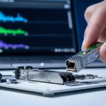
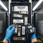
Pro Tip: In field audits, I’ve seen “compatible” modules pass basic link up tests but still produce elevated error counters at high temperature. The giveaway is usually DOM current or transmit power drifting toward the vendor’s internal limits. If your switch supports it, poll DOM frequently during a warm reboot or controlled heat soak; a stable link at room temperature is not the same as stable operation at peak chassis ambient.
Deployment scenario: how brand differences show up in a leaf-spine DC
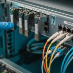
Consider a 3-tier data center leaf-spine design: 48-port 10G Top-of-Rack switches feeding 8-port 40G uplinks, then 100G spine interconnects. Suppose you run 48 x 10GBASE-SR links per leaf and use 2 x 40GBASE-SR4 uplinks per leaf, plus 4 x 100GBASE-SR4 per spine. Total optics count can exceed 1,000 modules across the fabric, which makes a transceiver brand comparison a reliability and operational cost exercise, not just a price-shopping task.
In one real rollout, the first week after cutover looked fine: all links came up, throughput matched line rate, and BER was within expected ranges. The issue appeared after a summer heat spike when ambient in front-of-rack reached 38 C and the hottest switch exhaust zones stayed near 55 C. A subset of lower-cost modules showed higher link error counters and intermittent CRC spikes during traffic bursts. The root cause was a combination of tighter optical power drift tolerance and less conservative transmitter aging behavior, compounded by marginal fiber patch loss. After swapping those brands to units with published DOM power diagnostics and stronger temperature characterization, the error counters stabilized.

Transceiver brand comparison: ranking quality, reliability, and price
A practical ranking method is to separate “works on day one” from “works for 3-5 years with predictable maintenance.” Start by mapping each brand to evidence: datasheet optical budgets, DOM behavior, and published compliance claims. Then validate with a pilot: run a controlled burn-in with your exact switch models and fiber plant.
Evidence sources you can use
- Vendor datasheets for transmitter output power, receiver sensitivity, and temperature grades
- Switch vendor compatibility guidance (often via transceiver support lists)
- DOM implementation consistency (threshold alarms, register mapping, and diagnostic readability)
- Field RMA patterns if you have access to internal warranty or service logs
- Independent vendor testing reports where available (tech media and lab measurements)
Concrete brand examples to anchor your evaluation
For mainstream optical modules, you will see enterprise and OEM ecosystem products like Cisco-branded optics (often based on third-party OEM designs). On the supplier side, common OEM optical module manufacturers include Finisar and its successor branding under Coherent-related structures (for example, parts like FTLX8571D3BCL show up in industry). Third-party resellers also sell SFP and QSFP optics under their own branding and under compatibility-tested programs (for example, FS.com SFP-10GSR-85 is a representative SKU style, and Cisco SFP-10G-SR is a representative OEM SKU style). Use these examples only as anchors; always verify the exact part number and DOM behavior for your switch.
From a transceiver brand comparison perspective, OEM and major-name suppliers often win on documentation quality and predictable thermal performance. However, third-party modules can be cost-competitive if they provide clear datasheets, DOM compliance, and a documented return policy. The “best” brand is the one that matches your switch optics expectations and your link budget margins.

Selection criteria checklist: decide with numbers, not assumptions
Use this ordered checklist when choosing a transceiver brand for a specific network segment. It is designed to prevent the most expensive mistakes: incompatibility, marginal link budgets, and poor thermal behavior.
- Distance and link budget: calculate worst-case fiber attenuation and connector/panel loss; do not rely on “reach marketing.”
- Correct media type: confirm OM3 vs OM4 and patch cord quality; multimode launch conditions matter at 850 nm.
- Switch compatibility: verify the exact switch model and port type support; some platforms have stricter EEPROM and optics policies.
- Data rate and form factor: confirm SFP+ vs SFP28 vs QSFP+ vs QSFP28, plus lane mapping for SR4 optics.
- DOM support and monitoring: ensure DOM registers are readable and alarms behave as expected in your network management system.
- Operating temperature grade: match your chassis ambient and airflow; consider industrial grade if you operate near upper limits.
- Vendor lock-in risk: compare replacement availability, lead times, and warranty terms against your spares strategy.
- Warranty and RMA process: confirm how fast you can get replacements and whether DOA returns are handled without downtime.
- Total cost of ownership: include failure rates, truck rolls, and downtime cost—not just unit price.
Common pitfalls and troubleshooting tips
Even experienced teams run into predictable failure modes. Below are common mistakes I’ve seen during deployments and migrations, with likely root causes and specific fixes.
Pitfall 1: “Link up” success but high CRC or errors under load
Root cause: marginal optical budget (patch loss, dirty connectors, or aging) combined with a module whose transmitter power drift is near its limit. Solution: clean connectors, measure link loss with an OTDR or certified power meter, then compare DOM TX power and bias/current trends at idle and during peak traffic. If DOM thresholds are too tight or telemetry is inconsistent, switch brands for that segment.
Pitfall 2: Intermittent compatibility failures after reboot
Root cause: EEPROM content or speed ID handling differences causing slower or failed optics initialization on certain switch firmware versions. Solution: update switch firmware to the version validated by your compatibility matrix, then try the same transceiver part number across multiple ports to isolate whether it is a port policy issue or a module behavior issue.
Pitfall 3: Thermal throttling or early aging in hot aisles
Root cause: using modules rated for commercial temperature in environments that regularly exceed the chassis design assumptions, plus restricted airflow from blocked front-to-back paths. Solution: measure actual inlet and exhaust temperatures (not just room temperature), ensure airflow baffles are installed, and move to industrial grade modules or adjust fan profiles. Validate with a burn-in test at peak ambient.
Pitfall 4: MPO/MTP polarity mistakes or lane mapping confusion
Root cause: incorrect MPO polarity adapters or wrong fiber mapping for SR4 optics (lane order matters). Solution: verify fiber polarity using a polarity tester, re-terminate or swap polarity adapters, and confirm lane mapping in the switch. If errors follow the same lanes, it is usually a cabling or polarity issue rather than a brand issue.
Cost and ROI note: what “cheaper” really costs
In many networks, the unit price difference between an OEM module and a third-party module can be meaningful, especially for QSFP28 100G SR4 and higher. Typical street pricing varies by region and volume, but a realistic budgeting approach is to compare unit cost plus warranty terms plus downtime cost. If a third-party brand saves 15-30% per module but increases RMA frequency or causes more truck rolls, the total cost of ownership can erase the savings.
For ROI, treat optics like other field-replaceable units: maintain spares sized to your failure rate and lead times. Also include power and cooling impacts indirectly: if marginal optics drive higher retransmissions or error recovery, you can increase switch CPU utilization and energy per useful bit, especially on oversubscribed segments.
FAQ
Which transceiver brand comparison method is most reliable: spec sheets or lab testing?
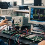
Use both, but prioritize lab testing with your actual switch models and fiber plant. Spec sheets tell you what is theoretically possible, while lab testing reveals DOM behavior, initialization quirks, and real BER under your power budget. The fastest path is a pilot with representative ports and your highest-loss patch panels.
Do third-party optics always work as well as OEM modules?
No. Many third-party optics are excellent, but performance depends on the exact OEM design, temperature characterization, and DOM implementation. If you cannot validate DOM telemetry and temperature behavior with your switch firmware, you should expect higher operational risk.
What DOM metrics should I monitor during acceptance testing?
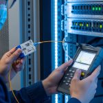
Monitor TX optical power, RX optical power (if supported), laser bias/current, and temperature. Also watch for threshold alarm events and error counters like CRC or FEC-related indicators on the switch. The goal is to ensure stable operation across idle and peak traffic at your measured ambient temperatures.
How do I validate compatibility quickly without buying a full inventory?
Buy a small batch of the candidate transceiver part number, test across multiple ports and a range of fiber runs, and run a burn-in at peak ambient conditions. If your switch vendor provides a compatibility list, use it to narrow candidates first, then validate the exact DOM behavior.
What is the biggest hidden cost in a bad transceiver choice?
Downtime and troubleshooting time are usually larger than the unit price difference. A brand that causes intermittent link drops can trigger repeated maintenance cycles, escalations, and extended outage windows, especially in high-availability architectures.
Should I mix transceiver brands in the same switch fabric?
It is usually best to standardize within a fabric segment to simplify monitoring and root-cause analysis. Mixing brands can be acceptable if they are verified equivalent in DOM behavior and optical budget, but it complicates trend analysis during incident response.
For a more targeted next step, compare your specific module type and switch model against a compatibility and DOM monitoring plan using fiber optic transceiver compatibility checklist. If you want fewer surprises, treat optics procurement as a small engineering project: verify specs, validate behavior, and record the metrics you will trust during troubleshooting.
Author bio: I build and troubleshoot optical links in operational data centers, focusing on measurable BER, DOM telemetry stability, and temperature margins. I document field lessons from deployments that include pilot testing, burn-in runs, and post-mortem analysis of link failures.