Your legacy network is humming along on 10G and 40G optics, but your CFO just discovered “400G” and now wants it yesterday. This article walks engineers through fiber upgrade strategies for migrating legacy systems to 400G fiber while keeping downtime small and blame assignments fun. You will get selection checklists, common failure modes, and a ranked summary so you can choose optics and cabling with confidence.
Top 7 fiber upgrade strategies for legacy systems to reach 400G
In a 400G migration, the fiber plant is usually the boss fight: patch panels, MPO trunks, polarity, dispersion, and connector cleanliness all matter. Start by mapping current lanes (10G/25G/40G) to the 400G transceiver interface your switches support, then decide whether you can reuse existing fiber or must add parallel strands. The best plans treat optics, patching, and operational change control as one system, not separate hobbies.
Inventory the fiber plant like a forensic accountant
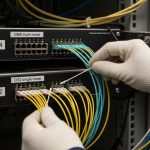
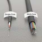
Before buying anything shiny, pull your as-built records and verify them with a test plan: link endpoints, fiber type (OM3/OM4/OS2), strand count, connector types, and patching topology. For 400G, you will often move from individual LC pairs to MPO/MTP fanouts that carry multiple lanes per cable. Measure with an OTDR or at least confirm loss with a light source and power meter; in practice, you want margin for aging and relabeling chaos.
- Key spec to capture: end-to-end insertion loss and worst-case patch loss.
- Most common legacy reality: “OM3 with random polarity” and “mystery jumpers.”
- Best-fit scenario: data centers with mixed OM3/OM4 and incomplete documentation.
- Pros: prevents buying the wrong reach optics; reduces field swaps.
- Cons: takes time; requires disciplined labeling.

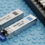
Choose 400G optics that match distance and fiber type
400G optics come in multiple flavors: coherent for long reach over OS2, and direct-detect for short reach over multimode and some single-mode cases. For typical enterprise and data center runs, you will likely choose either 400G-SR8 (multimode, MPO) or 400G-DR4/400G-FR4 (single-mode, depending on vendor and switch support). IEEE 802.3 specifies Ethernet PHY behavior, while vendor datasheets specify exact reach, wavelength, and power.
| 400G option (common naming) | Typical wavelength | Connector | Fiber type | Typical reach | Operating temp (example) | Notes / compatibility |
|---|---|---|---|---|---|---|
| 400G-SR8 (direct-detect) | 850 nm class | MPO-8 (often polarity-aware) | OM3 / OM4 | ~70 m over OM4 (varies by vendor) | 0 to 70 C (varies) | Requires clean MPO polarity and correct lane mapping |
| 400G-DR4 (direct-detect) | ~1310 nm class | 2x LC or MPO (varies) | OS2 | ~500 m (varies) | -10 to 70 C (varies) | Often easier with existing single-mode pathways |
| 400G-LR4 / coherent options | ~1310/1550 region (varies) | LC or coherent interface (vendor-specific) | OS2 | 10 km+ (coherent) | 0 to 70 C (varies) | Higher cost; more planning for transceiver support |
Field reality: switch vendor compatibility matters more than you think. Some platforms only accept specific optics families (even if “it should work”). Check the vendor optics matrix and whether your transceivers support the required digital diagnostics (DOM).
- Pros: avoids expensive fiber rebuilds when reach fits.
- Cons: vendor lock-in risk; multimode budgets can get spicy fast.

Plan polarity and MPO/MTP patching before you touch production
Polarity is where migrations go to die. Many 400G SR8 implementations use MPO-8 with lane groups that must align correctly. If you reuse existing MPO trunks, confirm whether your patching method is “A-to-A” or “A-to-B” and whether you need polarity adapters. Use a deterministic labeling scheme at both ends and verify with a microscope-grade inspection process for connector cleanliness.
Pro Tip: In the field, the fastest way to avoid a week of “it links but it flaps” is to standardize one MPO polarity method per site and document the adapter type used (including which side gets the polarity flip). If you mix methods across rows, your troubleshooting time becomes a lifestyle choice.
- Best-fit scenario: sites with existing MPO trunks and multiple patch panels.
- Pros: fewer link training failures; predictable cutovers.
- Cons: requires careful labeling and adapter inventory.
Stage the cutover with VLAN-aware change control
Layer 2 migration is not just optics: you are also moving traffic engineering, monitoring, and failure domains. Use VLANs and VRFs to isolate test traffic, then validate link stability, CRC/error counters, and queue behavior. For example, in a leaf-spine fabric, you can move one ToR pair at a time, keep uplinks in a dedicated VLAN for validation, and confirm ECMP behavior before expanding.
- Key step: pre-stage configs and verify port-channel/LAG behavior.
- Best-fit scenario: environments with strict change windows.
- Pros: reduces blast radius; easier rollback.
- Cons: requires good automation for consistent port setup.
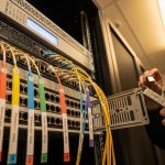
Upgrade patch panels and breakouts to match 400G lane density
Legacy panels often use LC patching with lots of individual jumpers. 400G frequently wants MPO trunks and fanouts, meaning your patching architecture must support higher density cleanly. Replace or supplement patch panels so MPO breakout ports are correctly spaced, labeled, and strain-relieved. If you try to “make it fit” with improvised jumpers, you will pay later in insertion loss and mechanical stress.
- Pros: reduces connector count and improves manageability.
- Cons: may require rack work and downtime for physical swaps.

Validate with link tests: optical power, BER proxies, and interface counters
After installation, validate with more than “link up.” Check optical receive power levels, DOM telemetry, and interface counters for errors. For multimode, pay special attention to whether your system is operating near its power budget; a marginal link can pass at first and fail under temperature drift. Run a short traffic burn-in and confirm that error rates stay stable.
- Best-fit scenario: new MPO trunks or reused legacy fiber with uncertain loss.
- Pros: catches problems before you declare victory.
- Cons: requires test tooling and disciplined measurement.
Choose transceivers carefully: OEM vs third-party and DOM support
For 400G, optics are expensive, and the “works on my bench” problem is real. OEM optics often integrate tightly with switch support policies, while third-party modules can be cheaper but may have compatibility caveats. Confirm that your switch supports the transceiver type and that DOM is enabled and readable; also verify whether the module supports required digital features per your platform.
- Examples you might see in the wild: Cisco-branded 400G optics, Finisar/II-VI variants, and FS.com modules such as 400G-SR8 families (model names vary by vendor catalog).
- Pros: can reduce upfront costs if compatibility is proven.
- Cons: higher risk of intermittent support issues; verify return policies.
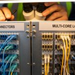
Real-world deployment scenario: legacy 40G ToR links to 400G spine
In a 3-tier data center leaf-spine topology, a team migrates 48-port 40G ToR switches to 400G uplinks across two stages. Each ToR has 4 uplink pairs originally on 40G QSFP+ over OM3, with patch panels using LC jumpers and mixed MPO trunks in a few rows. They inventory fiber, then decide to keep OM3 for SR8 where measured loss fits, while converting long runs to OS2 with DR4-style optics. During the first cutover, they move one leaf pair into a dedicated VLAN, validate traffic (including ECMP hashing distribution), and then expand to the remaining 22 leaves over two weekends.
Selection criteria and decision checklist (engineers actually use)
- Distance and reach: compare measured insertion loss to the optics budget with margin.
- Fiber type and bandwidth history: OM3 vs OM4 vs OS2; confirm actual plant condition.
- Switch compatibility: check the platform optics support list and required interface type.
- DOM and telemetry: ensure digital diagnostics are supported for monitoring and alerts.
- Operating temperature and airflow: confirm transceiver temperature range matches your rack conditions.
- Connector and polarity plan: define MPO/MTP polarity method and adapter usage.
- Vendor lock-in risk: weigh OEM vs third-party and confirm return/RMA terms.
- Cutover constraints: plan staged VLAN-aware changes and rollback triggers.
Common mistakes / troubleshooting tips for 400G fiber migrations
Polarity mismatch causing no-link or link flaps
Root cause: MPO/MTP polarity adapter not used (or wrong side used), lane mapping reversed, or mixed conventions across patch panels. Solution: re-verify MPO polarity end-to-end, standardize adapter type, and label both sides before reconnecting. Inspect connectors for damage and clean them with approved procedures.
Marginal optical budget on reused multimode fiber
Root cause: legacy OM3 fiber with higher-than-recorded patch loss, excessive bend radius history, or dirty connectors. Solution: measure receive power and end-to-end loss; if margin is thin, move to OS2 optics or replace high-loss jumpers and panels.
Assuming “any 400G-SR8” works with your switch
Root cause: platform-specific optics compatibility lists, different electrical interface expectations, or transceiver firmware behavior. Solution: use optics explicitly validated for your switch model and software version; test in a staging rack before field rollout.
Forgetting strain relief and mechanical stress on dense MPO trunks
Root cause: bending MPO trunks too tightly or stressing connectors during rack moves. Solution: enforce bend radius guidance from vendor datasheets, improve cable management, and re-verify optical power after physical adjustments.
Cost and ROI note: what budgets typically look like
400G optics can range from roughly hundreds to a few thousand dollars per module depending on reach and vendor, while fiber plant upgrades (patch panels, MPO trunks, adapters, cleaning/inspection tools) can add meaningful but more predictable costs. OEM optics may cost more upfront, but they often reduce downtime risk and support churn. Third-party modules can be cheaper, yet you should treat them like a science experiment: verify compatibility, monitor DOM health, and confirm RMA turnaround. ROI improves when your strategy reduces truck rolls, rework, and repeated cutovers.
Summary ranking table: best fiber upgrade strategies for 400G
| Rank | Strategy | Best for | Risk reduction | Time to implement | Cost impact |
|---|---|---|---|---|---|
| 1 | Inventory and verify fiber plant with measurements | Any migration, especially messy legacy sites | Very high | Medium | Low to medium |
| 2 | Choose optics by reach, fiber type, and switch matrix | Preventing “it should work” failures | High | Low | Medium |
| 3 | Standardize polarity and MPO/MTP patching | SR8 and dense MPO environments | Very high | Medium | Low |
| 4 | .wpacs-related{margin:2.5em 0 1em;padding:0;border-top:2px solid #e5e7eb} .wpacs-related h3{margin:.8em 0 .6em;font-size:1em;font-weight:700;color:#374151;text-transform:uppercase;letter-spacing:.06em} .wpacs-related-grid{display:grid;grid-template-columns:repeat(auto-fill,minmax(200px,1fr));gap:1rem;margin:0} .wpacs-related-card{display:flex;flex-direction:column;background:#f9fafb;border:1px solid #e5e7eb;border-radius:6px;overflow:hidden;text-decoration:none;color:inherit;transition:box-shadow .15s} .wpacs-related-card:hover{box-shadow:0 2px 12px rgba(0,0,0,.1);text-decoration:none} .wpacs-related-card-img{width:100%;height:110px;object-fit:cover;background:#e5e7eb} .wpacs-related-card-img-placeholder{width:100%;height:110px;background:linear-gradient(135deg,#e5e7eb 0%,#d1d5db 100%);display:flex;align-items:center;justify-content:center;color:#9ca3af;font-size:2em} .wpacs-related-card-title{padding:.6em .75em .75em;font-size:.82em;font-weight:600;line-height:1.35;color:#1f2937} @media(max-width:480px){.wpacs-related-grid{grid-template-columns:1fr 1fr}}