In multi-tenant buildings, the vertical riser fiber segment often determines whether your in-building network stays stable as loads grow. This article helps data center and telecom teams choose SFP transceivers for vertical and horizontal distribution, with practical engineering checks you can apply on day one. It is written for field engineers and network planners working with switches, patch panels, and optical budget constraints.
Vertical vs horizontal distribution: where vertical riser fiber changes the SFP match
When optical links traverse a building, the vertical riser fiber typically runs from telecom rooms to each floor, then hands off to horizontal runs to endpoints. In practice, vertical riser segments include more splices, more patching points, and more probability of installation variability than a short horizontal jumper. Those differences affect link budget, connector cleanliness risk, and the likelihood of marginal optical power readings. As a result, the SFP selection is not only about target distance; it is also about how much optical margin you preserve for aging and maintenance events.
For example, a typical floor plan may use 12-fiber or 24-fiber risers with LC trunking and ODF patching, then split to horizontal cables with additional connectors. Even if the horizontal distance is short, the end-to-end link includes the riser plus horizontal plus patch cords. Engineers often underestimate the compounded loss from repeated mated connectors and re-termination after tenant fit-outs.
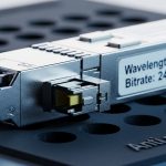
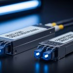
From an optical interface standpoint, many in-building deployments use 10G SFP+ SR (850 nm multimode) for short reach and 1G/10G SFP variants for copper alternatives. In higher-capacity upgrades, teams may migrate to 25G/40G over multimode or single-mode using SFP/SFP+ compatible optics depending on switch ASIC and port mode support. The key is aligning the SFP transceiver type with the fiber plant (OM3/OM4 multimode versus OS2 single-mode) and the actual measured loss.
Performance head-to-head: multimode SFP+ vs single-mode SFP for riser links
Below is a practical comparison you can use when the building plant includes a mix of multimode and single-mode fibers. The numbers reflect typical vendor class specs; your final answer must be verified against your as-built attenuation, splice loss, and connector count. Still, this head-to-head view captures the engineering tradeoff that matters most for vertical riser fiber distribution.
| Option | Typical SFP family | Wavelength | Target reach class | Fiber type | Connector | Optical power class (typical) | DOM | Operating temp (typical) |
|---|---|---|---|---|---|---|---|---|
| Multimode short-reach | 10G SFP+ SR | 850 nm | Up to 300 m (OM3) / 400 m (OM4) | OM3 or OM4 | LC | Tx power roughly -4 to +1 dBm; Rx sensitivity around -10 to -12 dBm (varies by vendor) | Common (not universal) | 0 to 70 C (often) |
| Single-mode long-reach | 1G/10G SFP (LX/EX) or 10G SFP+ LR/ER | 1310 nm (LX/LR) or 1550 nm (ER) | Up to 10 km (LR class) | OS2 | LC | Tx power often +0 to +3 dBm; Rx sensitivity around -18 to -22 dBm (varies) | Common | -5 to 70 C or wider (varies) |
In building riser scenarios, multimode SR can work well if the total end-to-end loss stays within the SR budget and the plant is clean and well-managed. However, it becomes fragile when the vertical riser has many patch points, when contractors add extra jumpers during tenant changes, or when the riser fibers are not the expected OM3/OM4. Single-mode optics usually offer more optical margin and greater tolerance for connector variability, but they require OS2 fiber and careful confirmation of wavelength compatibility.
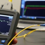
Pro Tip: In vertical riser fiber runs, the connector and splice count often consumes more link budget than the “distance” number on paper. Before swapping optics, count every mated LC/SC interface in the end-to-end path and request OTDR or at least certified attenuation per segment; otherwise an SR link can pass in the lab and fail after a single re-termination.
For reference, IEEE Ethernet optical link behavior is defined by the transceiver interface and link layer expectations, while the physical layer performance depends on the optical parameters and fiber characteristics. The baseline Ethernet PHY requirements for SFP-class optics align with IEEE 802.3 standards for optical Ethernet, and transceiver behavior is governed by vendor datasheets and SFF specifications. [Source: IEEE 802.3 Working Group overview] [[EXT:https://www.ieee802.org/3/]]
Compatibility and deployment: matching SFP optics to switch ports and riser cabling
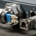
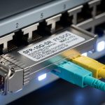
Switch compatibility is where many teams lose time. Not every SFP+ port accepts every vendor’s optics, especially when the switch firmware enforces EEPROM validation or when the optics do not meet the expected digital diagnostics format. In building distribution, that matters because vertical riser fiber may be reused for multiple future upgrades, and you want stable optics interchangeability across maintenance cycles.
For hands-on deployments, I have seen this exact failure mode: a switch model supports 10G SFP+ SR, but it rejects third-party optics that do not properly implement DOM EEPROM fields or that report out-of-range values. The physical layer never comes up, and the port stays down even though the optical connector is clean. The fix is to use optics explicitly validated for that switch family and to confirm that the SFP transceiver type matches the port speed and lane mapping.
Common validated examples include vendor-specific SR optics such as Cisco-branded modules and third-party modules that follow SFF and IEEE expectations. Examples engineers often stock include Cisco SFP-10G-SR and third-party optics like Finisar FTLX8571D3BCL or FS.com SFP-10GSR-85, but always verify switch compatibility and fiber type first. [Source: Cisco and Finisar product datasheets] [[EXT:https://www.cisco.com/]] [[EXT:https://www.lumentum.com/]]
Checklist to validate before you touch the vertical riser fiber
- Confirm fiber type: OM3/OM4 for 850 nm SR, OS2 for 1310/1550 nm single-mode.
- Measure end-to-end loss: include riser + floor patching + horizontal jumpers; do not rely on cable spec attenuation alone.
- Count connectors and splices: each mated connector and splice adds loss and contamination risk.
- Verify switch optical mode: speed, breakout settings, and port configuration must match the transceiver capability.
- Check DOM support: confirm whether the switch reads digital diagnostics and what alarms it triggers.
- Validate temperature range: in telecom closets with poor HVAC, confirm the transceiver operating range fits the environment.
- Assess vendor lock-in risk: test one optical vendor end-to-end before committing to bulk spares.
Cost and ROI: where the lowest unit price can raise total risk
Cost decisions for vertical riser fiber links are not just about the transceiver price. Total cost of ownership includes spares stocking, compatibility testing time, cleaning consumables, and the probability of future swaps due to fit-out changes. In many buildings, the telecom room experiences frequent re-patching, which increases the chance of connector contamination and intermittent optical faults.
Typical street prices vary widely by brand and speed. As a practical range from field purchasing patterns, 10G SFP+ SR optics are often in the $40 to $150 per module range, while single-mode LR/LX optics can be $80 to $250 depending on reach class and vendor. OEM optics may cost more, but they often reduce compatibility surprises and speed up acceptance testing. Third-party options can be cost-effective if you validate them with your switch model and document optical power and DOM readings.
ROI also depends on your upgrade path. If you expect tenant growth and potential bandwidth increases, investing in OS2 single-mode risers can reduce future forklift upgrades, because single-mode optics cover longer reach and support multiple link classes with less constraint. The limitation is that you must have OS2 fiber in place; if your riser is multimode only, you may be locked into multimode optics for that segment unless you redeploy fiber.
Common mistakes and troubleshooting for vertical riser fiber SFP links
Even solid designs fail during installation. The sections below list concrete mistakes I have seen in buildings and the root cause plus solution. Use these as a rapid triage playbook when a port does not come up or link quality degrades.
Link stays down after optics install
Root cause: switch port does not support the transceiver type at the configured speed, or the optics EEPROM/DOM fields fail validation. Sometimes the module is the right fiber type but the wrong wavelength class for the deployed plant.
Solution: verify port configuration, then confirm the transceiver is the correct class (850 nm SR for OM3/OM4, 1310 nm for OS2 LX/LR). If using third-party optics, test with a known-compatible OEM module to isolate compatibility versus fiber issues.
Link comes up, then flaps during maintenance or re-patching
Root cause: connector contamination caused by repeated handling in the riser patch panel. Dust on LC end faces can create intermittent signal loss, especially on marginal optical budgets.
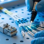
Solution: clean connectors with lint-free wipes and approved cleaning tools, then inspect with a microscope or fiber scope. Re-terminate only if inspection shows scratches or persistent contamination; otherwise, improving cleaning discipline often resolves the issue.
OTDR shows high loss at multiple points but cable distance seems short
Root cause: loss is concentrated in patch cords, adapter plates, or splice trays rather than along the fiber span. In vertical riser fiber deployments, repeated floor-level patching can add unexpected connectors and splices beyond the original design.
Solution: build an end-to-end loss worksheet from as-builts, then correlate it to OTDR event maps. Replace high-loss jumpers and confirm adapter type and cleanliness; also verify that the expected fiber pair is used (a mispairing swap can produce confusing results).
Multimode SR fails after a tenant fit-out change
Root cause: the riser fiber was assumed to be OM4 but was actually OM2/unknown, or the installer used the wrong patch panel labeling. SR optics can still light up briefly but fail as the system reaches worst-case conditions.
Solution: run fiber identification and confirm core size and bandwidth class where feasible. Update labeling and labeling verification procedures for the patch panels serving the riser and each horizontal run.
Decision matrix: choose the right transceiver path for your riser and floors
Use this matrix to decide between multimode SR and single-mode options for vertical riser fiber distribution. It focuses on engineering constraints rather than marketing reach claims.
| Scenario | Riser fiber plant | Typical end-to-end distance | Best-fit option | Why |
|---|---|---|---|---|
| New in-building LAN, short floor runs, stable patching | OM4 multimode riser | Under SR class reach with margin | 10G SFP+ SR (850 nm) | Lower cost and simpler optics; keep margin by controlling connectors and splices |
| Frequent re-patching due to tenant turnover | OM4 or mixed multimode | Near the SR budget | Consider single-mode migration or higher-margin optics if OS2 exists | Single-mode generally tolerates loss variability better; multimode can be sensitive to contamination |
| Long vertical runs or uncertain as-built lengths | OS2 single-mode | Multi-kilometer including patching | 10G SFP+ LR/LX (1310 nm) | More optical budget headroom; easier growth path for additional floors |
| Upgrade path to higher speeds with minimal re-cabling | OS2 single-mode | Varied by tenant | Single-mode optics aligned to switch roadmap | Reduces forklift risk; supports broader transceiver class options over time |
Which option should you choose?
If you have confirmed OM4 vertical riser fiber and your measured end-to-end loss leaves margin after counting connectors and splices, choose multimode SR SFP+ for the cost and operational simplicity. If your building has frequent tenant changes, inconsistent patching practices, or uncertain fiber identification, prioritize single-mode optics on OS2 vertical riser fiber where available to increase tolerance and reduce intermittent faults. If you are planning a phased refresh, I recommend standardizing optics with DOM support and validating one optics vendor end-to-end to reduce acceptance delays during future floor rollouts.
Next step: review your optical budget and connector inventory using fiber-optic-link-budget-checklist so you can select SFP modules based on measured loss rather than assumed distance.
FAQ
Q: What does “vertical riser fiber” mean in building networks?
It is the backbone fiber that runs vertically between telecom rooms or riser closets, carrying traffic to each floor’s horizontal distribution. Because riser paths include multiple patching and splicing points, they typically have higher variability in loss than a short horizontal jumper.
Q: Can I use 850 nm SFP SR optics over any fiber?
No. 850 nm SR SFP optics require multimode fiber with the correct bandwidth class, typically OM3 or OM4. If your riser plant is OS2 single-mode, using SR optics will not work correctly, and link failures can occur even if connectors are physically compatible.
Q: How do I verify DOM support and compatibility?
Check the switch vendor optics compatibility list and confirm the transceiver EEPROM supports the expected DOM fields. In the field, I validate by inserting the module, reading diagnostics, and verifying that alarms and thresholds behave as expected under normal optical levels.
Q: Why do links flap after re-patching in the riser patch panel?
The most common cause is connector contamination or a marginal optical budget. Cleaning and inspection with a fiber scope often resolves the issue faster than swapping optics repeatedly.
Q: Are third-party SFP modules safe for production use?
They can be, but only after you validate them with your specific switch models and document DOM and link behavior. OEM optics typically reduce compatibility surprises, but third-party optics can lower TCO when acceptance testing is strict and consistent.
Q: What is a reasonable maintenance approach for vertical riser fiber?
Use a controlled cleaning workflow, track connector usage, and periodically re-certify critical links using OTDR or certified attenuation tests. Keep spare optics that are pre-validated for your switch platform to minimize downtime during tenant changes.


Author bio: I am a telecom engineer who has deployed and tested 5G fronthaul and in-building optical networks, including DWDM/SDH backhaul planning and PON-to-enterprise handoffs. I write from field experience using measured OTDR traces, switch optics compatibility testing, and connector cleanliness verification.