When your leaf-spine fabric suddenly drops a port, “fiber is fine” is often the last assumption you should make. This article helps network and field engineers run a disciplined data center repair workflow for SFP link failures, using measurable checks that match how real optics behave in the rack. You will compare likely SFP scenarios side-by-side, see what to verify first, and avoid the costly mistakes that turn a 20 minute fix into a multi-day outage.
Repair reality check: SFP link failures you can prove, not guess
In the field, most SFP link failures fall into a few repeatable categories: optical power too low, mismatched optics type, connector contamination, or switch-side interface/DOM misread. IEEE 802.3 defines electrical and optical behavior for Ethernet PHYs, while vendor datasheets define transceiver electrical limits, DOM interpretation, and supported temperatures. For data center repair, your fastest path is to treat the SFP as a measurable system: link state, receive power, DOM diagnostics, and physical cleanliness.
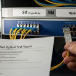
Start by capturing the evidence your switch already knows: interface admin state, link status, negotiated speed, and any alarms such as LOS, LOF, or “unsupported transceiver.” Then verify optics compatibility and fiber path: correct wavelength (for example, 850 nm SR vs 1310 nm LR), correct polarity, and correct fiber type. If you have access to an optical power meter, you can confirm whether the failure is “transmit is weak,” “receive is weak,” or “nothing is getting through.”

Head-to-head: Replace the SFP, clean the fiber, or reconfigure optics?
Engineers often jump straight to replacement, but in many data center repair events the SFP is innocent. The right choice depends on which symptom set you see on the switch and optics. Below is a practical comparison of the most common repair paths, with what you should measure and what typically causes the issue.
| Repair Option | What You Observe | Key Checks (Measured) | Typical Root Cause | Best For |
|---|---|---|---|---|
| Swap SFP with known-good | Port down or flapping; DOM may show low RX power or “no diagnostics” | Compare RX power and link stability; confirm DOM values update | Transceiver aging, damaged optical bench, ESD damage | Suspected module failure, repeated LOS alarms |
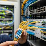
| Clean connectors and repatch | Port down after a move; neighbors work; no DOM alarms beyond RX low | Visual inspection with scope; verify stable RX power after repatch | Connector contamination, micro-scratches, dust | Intermittent links or sudden failures with no config change |
| Verify optics type and wavelength | “Transceiver not supported” or link never comes up | Confirm 850 nm vs 1310 nm; check switch compatibility list | Wrong SFP model, wrong reach class, vendor mismatch | After parts swap, inventory mix-ups, RMA returns |
| Check polarity and fiber mapping | Link up then fails under load; extreme RX power swings | Measure RX power; confirm Tx-to-Rx mapping and polarity labels | Reversed polarity, wrong duplex pair, crossed patch cords | When physical patching changed or trays were reworked |
What “good evidence” looks like
A disciplined workflow uses a small number of high-value measurements. If your switch exposes DOM, record RX power (dBm), TX bias current, and temperature. If RX power is far below the expected range for that transceiver class, cleaning or polarity is often the fastest win. If DOM values look normal but the module fails to bring the link up, that strongly points to a defective optic.
Pro Tip: If you see the SFP DOM update instantly after insertion but RX power remains near the noise floor, suspect optics-to-fiber alignment problems (polarity or connector contamination) before you condemn the module. In practice, a “new” SFP can still fail if the patch panel pair is contaminated or reversed.
Specifications that matter during data center repair: SR, LR, and power budget
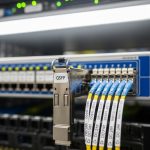
Not all SFPs are interchangeable, even when they look identical. For Ethernet optics, the key parameters are wavelength, reach, receiver sensitivity, connector type, and temperature range. During data center repair, you need to confirm you matched the SFP to the switch port’s supported optics class and the fiber plant’s loss budget.
Here is a comparison of common SFP categories engineers swap during troubleshooting. Exact values vary by vendor and exact part number, so always confirm against the SFP datasheet and the switch vendor’s compatibility guidance.
| Transceiver Class (Examples) | Wavelength | Typical Reach | Connector | Operating Temp | Power/Diagnostics |
|---|---|---|---|---|---|
| 10GBase-SR (e.g., Cisco SFP-10G-SR, Finisar FTLX8571D3BCL, FS.com SFP-10GSR-85) | 850 nm | Up to ~300 m over OM3/OM4 multimode (class-dependent) | LC duplex | 0 to 70 C typical (varies) | DOM: RX/TX power and temp commonly supported |
| 10GBase-LR (single-mode) | 1310 nm | Up to ~10 km | LC duplex | -5 to 70 C or wider (depends) | DOM: RX bias and temperature commonly supported |
| 1GBase-SX (legacy multimode) | 850 nm | Up to ~550 m | LC duplex | 0 to 70 C typical | DOM availability varies |
How to use power budget logic fast
Without a meter, you can still do a structured pass. Confirm that the fiber is OM3/OM4 for SR, that the patch cords are the correct type, and that the link is using the intended wavelength. With a meter, compare measured RX power to the transceiver’s sensitivity curve from the datasheet. If RX power is marginal, cleaning and repatching often yields an immediate improvement because connector loss dominates short links.

Compatibility and DOM support: avoiding “it fits but it won’t link”
Switch ports can be picky about optics vendor IDs, DOM format, and vendor-specific thresholds. During data center repair, you may see errors like “unsupported transceiver” even when the SFP is electrically correct for the PHY. Some switches also enforce optics safety limits or require specific DOM calibration ranges.
To reduce risk, align your replacement strategy with the switch model and optics ecosystem. Use the switch vendor’s compatibility list where available, and verify whether the port supports third-party optics and which DOM fields it expects. In mixed networks, an SFP that works in one switch may refuse to negotiate in another due to DOM interpretation or threshold differences.
Decision checklist engineers actually follow
- Distance and reach class: Confirm SR vs LR, and ensure the fiber plant matches (multimode OM3/OM4 vs single-mode).
- Link symptoms: LOS/LOF alarms, RX power near floor, or “unsupported transceiver” messages.
- Switch compatibility: Check the port’s optics support matrix and DOM expectations.
- DOM visibility: Verify RX/TX power, temperature, and alarm flags update immediately after insertion.
- Operating temperature: Ensure the replacement SFP meets the cage and ambient conditions (especially in high-density rows).
- Vendor lock-in risk: Decide whether to standardize on OEM, or qualify third-party optics with a test plan.
Common pitfalls and troubleshooting tips during data center repair
Most outages are avoidable with a few disciplined checks. Below are concrete failure modes you can recognize quickly, along with root causes and fixes.
Pitfall 1: Replacing the SFP without checking RX power trend
Root cause: The link failure is caused by fiber loss, contamination, or polarity, not the module. A new SFP still sees the same low RX power and remains down. Solution: Record RX power from DOM (or measure with an optical power meter) before and after cleaning or repatching.
Pitfall 2: Polarity reversal during repatch
Root cause: Duplex LC polarity is reversed (Tx connected to Tx). This can lead to “no link” or unstable behavior under load. Solution: Use consistent labeling on patch cords, verify Tx-to-Rx mapping, and recheck polarity at the patch panel, not just at the transceiver.
Pitfall 3: Mixing multimode and single-mode optics by wavelength
Root cause: Installing 850 nm SR SFP into a single-mode path (or vice versa) causes severe attenuation and link failure. Solution: Confirm wavelength and fiber type before inserting. Treat any “it looks similar” SFP as suspect until verified.
Pitfall 4: Ignoring connector cleanliness
Root cause: Dust films or micro-scratches on LC endfaces can add several dB of loss, pushing marginal links over the edge. Solution: Inspect with a fiber scope, clean with lint-free wipes and proper solvent or cleaning cassettes, then repatch and recheck RX power.

Cost and ROI: OEM vs third-party optics for repair speed
In many data centers, optics spend is small compared to labor and downtime, but repair decisions can still affect TCO. OEM SFPs typically cost more per unit, while qualified third-party options can reduce purchase costs. Field experience shows that the real ROI comes from reducing repeat failures: a slightly cheaper module that causes rework can cost more in engineer hours.
Typical street pricing for 10G SFP modules varies by reach class and quality tier, often landing roughly in the $40 to $150 range for common SR parts and higher for long-reach or higher-spec temperature variants. For TCO, include: the probability of repeat failures, inventory holding costs, and whether your switch supports third-party optics without “unsupported transceiver” events. If your environment is high-density and you need fast swap-and-verify, standardizing on a small set of compatible part numbers can cut repair time and reduce downtime risk.
Which option should you choose?
If you are doing data center repair during an active outage, choose the fastest evidence-driven path: check DOM RX power and link alarms first, then either clean/repitch or swap with a known-good module. For teams with strict compatibility requirements, start with OEM or a pre-qualified optics list to avoid DOM and support issues. If you have reliable fiber hygiene, stable switch compatibility, and a qualified third-party supply chain, third-party optics can be a strong cost reducer without sacrificing performance.
Use this quick recommendation by reader type: if you are a field engineer, prioritize measurable RX power checks and connector inspection; if you are a network admin, prioritize compatibility and DOM visibility to prevent “works elsewhere” surprises; if you are a procurement lead, prioritize qualified SKUs and standardized part numbers to lower repeat repair rates. Either way, the best outcome comes from pairing the right optics selection with disciplined troubleshooting evidence.
FAQ
What measurements should I record during data center repair for SFP link failures?
Record the interface link state, any LOS/LOF alarms, and DOM values such as RX power, TX bias current, and temperature. If you have an optical power meter, measure RX power at the transceiver after repatching. This evidence typically identifies whether the issue is fiber loss/contamination or a defective optic.
How do I know whether to clean fiber or replace the SFP?
If RX power is low but DOM updates normally, cleaning and repatching are often the fastest fix. If the module fails to bring link up and DOM indicates abnormal diagnostics (or no reliable updates), swapping with a known-good SFP is more likely to work. Always verify polarity and wavelength before condemning hardware.
Are third-party SFPs safe for data center repair?
They can be, but only if they are qualified for your switch model and support the required DOM behavior. Some platforms enforce optics compatibility lists and may reject modules that do not match expected thresholds. Test replacements in a controlled maintenance window before scaling.
What are the most common reasons SFP links flap?
Connector contamination, marginal power budget, or intermittent polarity issues are the usual causes. Thermal stress can also contribute in high-density cages if the module’s operating temperature range is exceeded. Use RX power trend and visual connector inspection to narrow it down quickly.
Which standard should I reference when troubleshooting Ethernet optics behavior?
IEEE 802.3 covers Ethernet PHY behavior at the link layer, while vendor datasheets define optical parameters like sensitivity and DOM alarms. For cabling and structured installation practices, consult ANSI/TIA guidance on fiber handling and installation. Use these references to interpret measurements correctly.
Where can I confirm my optics reach and power budget expectations?
Use the exact SFP datasheet for receiver sensitivity and maximum link loss assumptions, then compare against your fiber plant documentation. If you do not have loss data, optical measurement after cleaning and repatching provides the fastest confirmation. For compatibility, cross-check with the switch vendor’s optics list.
Updated on 2026-04-30 with field-tested troubleshooting priorities for SFP link failures. For related repair workflows, see fiber optic cleaning for high-density data centers and tighten your next outage response loop.
Author bio: I have deployed and repaired 1G/10G and higher Ethernet optical links in multi