If you are rolling out SFP-based connectivity across a multi-row data hall, the bottleneck is often not the optics, but the fiber handling and patching time. This article helps network and facilities engineers plan, install, and validate a data center fiber assembly strategy using pre-terminated links designed for predictable polarity, bend radius, and fast turn-up. You will get a practical step-by-step implementation guide, a troubleshooting playbook, and selection criteria grounded in real switch/transceiver constraints.
Prerequisites: what you must confirm before you order
Pre-terminated fiber assemblies reduce field labor, but only if your physical layer assumptions match what your SFP transceivers and patching plan expect. Before procurement, confirm optics type (SR vs LR), connector standard, polarity scheme, and the exact patch panel and splice tray layout. In my deployments, missing one of these inputs causes rework even when the assemblies test “green” on day one.
Inputs to gather (field checklist)
- Switch model and port type: e.g., Cisco Nexus 9K (SFP/SFP+), Arista 7050X (SFP+), or Juniper QFX (SFP+), including whether the vendor expects MPO-to-duplex mapping for SR.
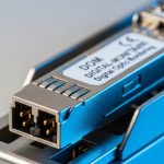
- Transceiver type: typical SR examples are Cisco SFP-10G-SR, Finisar FTLX8571D3BCL, or FS.com FS SFP-10GSR-85.
- Fiber plan: OM3 vs OM4, expected reach budget, and whether you have a clear-path loss model including patch cords.
- Connector and polarity: LC duplex vs MTP/MPO pre-terminated trunks, and polarity method (Method A/B or vendor-specific duplex mapping).
- Environmental constraints: operating range, max cable jacket temperature, and routing bend radius requirements.
Expected outcome: You have a complete BOM and layout assumptions so the pre-terminated data center fiber assembly matches your SFP port mapping on the first install.

Step-by-step implementation: deploy pre-terminated assemblies for SFP ports
The fastest turn-ups happen when you treat pre-terminated data center fiber assembly as a governed physical layer object: known length, known polarity, and tested continuity before it reaches the rack. Use the steps below to build from design to validation without “trial and error” patching.
— Lock the link budget and fiber type
For SR SFPs (850 nm), ensure OM4/OM3 selection matches your planned reach and expected losses from patch cords and consolidation points. In practice, I model worst-case loss using vendor link specs plus typical patch cord loss and connector loss. If you are unsure, request vendor test results (OTDR or insertion loss measurements) per assembly.
Expected outcome: A documented loss budget that your assemblies will meet with margin.
— Choose connector format and polarity mapping
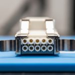
Decide whether you will terminate at the rack as LC duplex (common for individual SFP ports) or use MTP/MPO trunks between rows and fan out to LC patch cords. Pre-terminated assemblies can be manufactured with deterministic polarity, but only if you specify the polarity method and mapping in the order. For MTP/MPO systems, confirm how your patching strategy aligns with the transceiver transmit/receive expectations.
Expected outcome: A polarity-consistent plan that avoids swapped Tx/Rx.
— Order assemblies with factory test documentation
Request factory test data for each fiber pair, including insertion loss and return loss where applicable. Many vendors provide per-assembly reports and fiber identification labels so you can match ends to the patch panel without hunting. This is where pre-terminated data center fiber assembly provides measurable risk reduction: you eliminate most field termination variables.
Expected outcome: Traceability from factory test to rack port assignment.
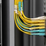
— Install with controlled handling and labeling
Mount patch panels, route the assemblies through trays, and keep bend radius within the manufacturer’s spec. Avoid tugging at connectors; terminate routing first, then remove dust caps right before mating. Label both ends with assembly ID and port mapping to support future moves/adds/changes.
Expected outcome: Clean installation with minimal connector stress and audit-friendly labeling.
— Validate with optical checks before full traffic
Before enabling production traffic, perform continuity verification and then bring up the link using SFP diagnostics (DOM if supported). In a real leaf-spine roll-out, we typically validate link up time and optical power levels per port, then run a short packet test window to confirm no intermittent errors.
Expected outcome: Confirmed link establishment and stable optical parameters.

Technical specifications: what matters for SFP SR deployments
Not all pre-terminated data center fiber assembly products are equivalent. The critical variables are wavelength compatibility, fiber type (OM3/OM4), connector style, and environmental survivability during installation. Below is a practical comparison for common 850 nm SR SFP and typical assembly attributes.
| Parameter | Typical SFP SR Target | Pre-Terminated Assembly Considerations |
|---|---|---|
| Data rate | Up to 10G per SFP (e.g., 10GBASE-SR) | Confirm transceiver compatibility with your switch and optics vendor |
| Wavelength | 850 nm | Assembly must be tested at the same wavelength used by the optics |
| Fiber type | OM3 / OM4 MMF | Match assembly fiber type to your plant fiber type to avoid margin loss |
| Connector | LC duplex at the SFP patch point | Specify end-face geometry and polish type; verify dust-cap handling |
| Reach (typical) | OM4 often supports farther than OM3 for SR-class links | Use factory insertion loss data plus patch cord losses |
| Operating temperature | Varies by cable construction | Ensure jacket and connector ratings cover your data hall profile |
| Polarity | Tx/Rx must map correctly | Vendor must apply the specified polarity method during pre-termination |
Reference points: IEEE 802.3 defines the optical Ethernet physical layer behavior and link requirements for 10GBASE-SR-class optics; transceiver vendors publish link budgets and DOM behavior. For standards context, see [Source: IEEE 802.3]. For vendor DOM and optical power behavior, see the specific SFP datasheets for your transceiver models.
Pro Tip: In field installs, the most time-consuming failures are not “bad fiber,” but polarity and mapping mismatches between pre-terminated trunks and rack patch panels. The fastest fix is to validate Tx/Rx mapping using a known-good transceiver and optical power readings from DOM before you start swapping patch cords blindly.
Selection criteria: decision checklist engineers actually use
When you choose a pre-terminated data center fiber assembly supplier or configuration, you are optimizing for predictability, testability, and low rework probability. Use this ordered checklist during RFQ and final review.
- Distance and reach margin: confirm OM3 vs OM4, expected patch cord count, and insertion loss budget.
- Switch compatibility: verify the SFP model and vendor interoperability with your switch platform.
- Connector standard: LC duplex vs MTP/MPO fan-out; confirm polish type and end-face inspection approach.
- DOM and link diagnostics: ensure your transceivers expose optical power and temperature so you can detect marginal links early.
- Factory test support: require per-assembly test reports (insertion loss/return loss, continuity) and fiber ID labeling.
- Operating temperature and handling: confirm cable jacket and connector rating matches your installation environment.
- Vendor lock-in risk: reduce future rework by using standard connector formats and polarity conventions documented in your drawings.
Expected outcome: A configuration that minimizes install time and maximizes predictable optical link performance.

Common mistakes and troubleshooting (top failure modes)
Even with factory pre-termination, errors happen in integration. Below are three common failure modes I have seen during SFP cutovers, with root cause and corrective actions.
Failure 1: Link does not come up after patching
Root cause: Tx/Rx polarity mismatch or reversed duplex mapping between assembly ends and patch panel. Solution: Use a known-good SFP and check DOM optical receive power; then swap the patch cord direction or re-terminate using the documented polarity method.
Failure 2: Link flaps under load
Root cause: Micro-bending from routing outside bend radius, or connector stress from pulling at the jacket during installation. Solution: Inspect routing paths, re-seat connectors, and correct tray routing; then re-run optical diagnostics and a short traffic test window.
Failure 3: High loss vs expected factory values
Root cause: Wrong fiber type (OM3 vs OM4) or excessive number of patch points beyond the loss model. Solution: Compare factory insertion loss report to field measurements (where available), verify patch cord count, and update the loss budget; replace with assemblies that match fiber type and length.
Cost and ROI note: when pre-terminated wins
Pricing varies by connector type, length, and factory test reporting. In many North American data center projects, pre-terminated assemblies for rack-to-row runs commonly land in a range of roughly $30 to $120 per link for LC duplex configurations, with higher costs for complex MTP/MPO fan-outs and shorter lead times. The ROI typically comes from reduced field labor and lower rework: a single avoided truck roll or termination failure often outweighs the incremental unit cost.
TCO reality: Third-party assemblies can be cost-effective, but only if they provide comparable factory test data and polarity documentation. OEM-like assemblies may cost more, yet they reduce integration risk when your platform has strict optical qualification expectations.
FAQ
What is a data center fiber assembly in SFP deployments?
It is a pre-built fiber interconnect, usually with factory-terminated connectors and labeled fiber IDs, designed to connect SFP transceiver ports to patch panels or consolidation points. In pre-terminated form, it reduces field termination variability and supports faster, more repeatable turn-up.
Do I need DOM support to validate a pre-terminated assembly?
DOM is not strictly required for link establishment, but it is strongly helpful for troubleshooting. With DOM, you can monitor receive optical power, temperature, and sometimes vendor-specific diagnostics to confirm you have margin rather than a borderline link.