Extended reach optics are where “it should work” meets “why is the link flapping at 2 a.m.?” This article helps data center and network engineers choose optical solutions for longer fiber spans without sacrificing stability, cooling headroom, or operational sanity. You will get a top-N checklist, a specs comparison table, and field-tested troubleshooting that matches what actually happens in racks full of leaf-spine gear.
Top 7 extended reach optical solutions reality checks
When you push beyond standard reach, you fight budget: optical power, dispersion, connector loss, and even how dusty your patch panels are. The trick is to pick transceivers and optics that match IEEE-defined behavior and your specific fiber plant. In practice, engineers also balance thermal limits, DOM telemetry support, and vendor interoperability quirks. Below are the seven checks that prevent most extended-reach link drama.
Distance math: budget your photons like it is payroll
Extended reach starts with a link budget, not vibes. For 10GBASE-LR style optics, reach is not just fiber length; it is transmit power minus receive sensitivity minus losses from fiber attenuation, connectors, splices, and patch cords. If your design assumes 0.3 dB/km but your actual plant is closer to 0.45 dB/km, you just erased margin you will never get back. Always calculate worst-case and allow a maintenance margin for re-patching and aging.
Practical field example
In a 3-tier data center leaf-spine topology, a team extended a 10G uplink between two suites across a routed corridor. They planned 2 km of OM3-to-OM4 conversion plus 12 m of patching, but the real loss was dominated by high-mismatch MPO trunks and two extra interconnect panels. The link came up at first, then degraded under higher temperature because the transceiver output and receiver margin tightened.
- Pros: Prevents surprise failures during commissioning
- Cons: Requires accurate as-built fiber loss data
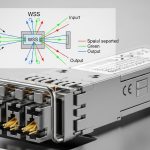
Wavelength and dispersion: match fiber type or suffer
Extended reach often means longer wavelength operation and tighter tolerance on dispersion. Single-mode links (1310/1550 nm depending on standard) are designed to handle dispersion differently than multimode. If you try to stretch multimode beyond its validated reach, differential mode delay and modal power distribution do the “surprise party” thing. For single-mode, you must also respect fiber chromatic dispersion limits for the chosen data rate and modulation.
What engineers verify
Check that your transceiver wavelength matches your fiber plant (single-mode vs multimode), and confirm the standard family (for example, 10GBASE-LR vs 10GBASE-ER, or higher-rate equivalents). Then verify whether your vendor supports the specific optic type for that fiber class. IEEE 802.3 defines optical parameters, but deployments still diverge due to patching and connector quality.
- Pros: Fewer “it works on the bench” incidents
- Cons: Limits flexibility if your fiber plant is mixed
Specs comparison that matters: reach, power, connector, and DOM
Not all extended reach optics are created equal. Some modules are rated for long reach but assume specific connector cleanliness and low-loss patching. Others are thermally fine but have weaker receive sensitivity or conservative transmit power. Use a side-by-side comparison to ensure you are buying the right class of module for your link budget.
| Module example | Data rate | Wavelength | Target reach | Connector | Operating temp | Typical power class |
|---|---|---|---|---|---|---|
| Cisco SFP-10G-SR (multimode reference) | 10G | 850 nm | ~300 m (spec dependent) | LC | 0 to 70 C | Low to moderate |
| Finisar FTLX8571D3BCL (10G ER class) | 10G | 1550 nm | ~40 km (class) | LC | Commercial/industrial variants | Moderate |
| FS.com SFP-10GSR-85 (10G SR reference) | 10G | 850 nm | ~300 m (spec dependent) | LC | Commercial/industrial variants | Low to moderate |
| Typical 40G LR4 / ER4 extended options (QSFP+) | 40G | 1310 nm (LR4) or 1550 nm (ER4 class) | ~10 km to 40 km (class) | MPO-12 | 0 to 70 C or wider with industrial | Higher than SFP |
Note: exact reach varies by vendor and compliance testing. For extended reach, always read the module datasheet and match it to the exact transceiver type supported by your switch.
Authority note: optical interfaces are standardized through IEEE 802.3 families for Ethernet optics. For transceiver behavior, consult the vendor datasheets and the applicable IEEE references. IEEE 802.3 standards portal [Source: IEEE Standards].

- Pros: Reduces “wrong module” swaps during rollout
- Cons: Datasheets can hide assumptions about patch loss
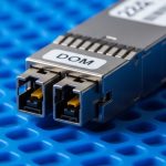
DOM telemetry: use it like a seatbelt, not a decoration
Extended reach links benefit from real-time telemetry via Digital Optical Monitoring (DOM). DOM provides values such as transmit power, received power, laser bias current, and temperature. In field operations, those numbers are gold when diagnosing marginal links that fail only under specific thermal conditions or after maintenance. However, compatibility varies: some switches read DOM differently, and some third-party optics may implement DOM behavior imperfectly.
What to collect during commissioning
Before you declare victory, record baseline DOM values and link error counters at steady state. Then repeat after planned temperature soak or fan-profile changes. If you see received power drifting toward the threshold, you have time to clean connectors, reduce patch loss, or swap the optic before the network starts improvising.
Pro Tip: Many extended reach failures are not “bad optics,” but cleanliness and patch loss. If your received power margin shrinks by more than a couple of dB after a maintenance window, treat connector cleaning and patch cord verification as a first-line fix before replacing modules.
- Pros: Faster root-cause with quantitative evidence
- Cons: Not all optics provide identical DOM granularity
Thermal behavior: the optics are small, the heat is not
Extended reach modules can run hotter depending on wavelength and laser drive current. In dense racks, even a slight airflow change can push transceivers toward their operating temperature ceiling. When that happens, optical output and receiver sensitivity can shift, especially in high-speed optics with tighter margins. In one deployment, a new exhaust fan schedule raised inlet temperatures by 4 C; the link started flapping within 48 hours.
Rack planning checks
Confirm airflow direction, verify baffle integrity, and measure inlet temperatures at the exact switch line cards that hold the optics. Also check that your optics are rated for your environment: commercial modules are often 0 to 70 C, while some deployments need wider industrial ranges. If you are running high-density 40G/100G, thermal margins are not optional.
- Pros: Prevents intermittent errors that waste nights
- Cons: Demands accurate environmental measurement

Fiber plant realities: connectors, splices, and MPO chaos
Extended reach magnifies every loss factor. A single dirty connector can add enough attenuation to kill your margin, particularly at higher data rates. MPO-based optics (common in QSFP and higher density) also add alignment sensitivity: polarity, keying, and endface cleanliness all matter. When engineers say “the fiber is fine,” it usually means it passed an old test that did not reflect current patching or a changed polarity requirement.
Field verification steps
Inspect and clean connector endfaces with the right tools, then verify polarity using your patching scheme. Re-test with an OTDR or qualified optical power meter for the exact link path. For MPO, confirm correct polarity mapping and endface inspection on every interface, not just the far end.
- Pros: Improves reliability without changing electronics
- Cons: Takes time during maintenance windows
Compatibility and vendor lock-in: plan for interoperability pain
Switch vendors sometimes enforce optical compatibility via firmware checks, DOM thresholds, or EEPROM profiles. That means a “standards compliant” optic may still refuse to initialize or may run at reduced margin. Extended reach optics are particularly sensitive because the receiver margin is tighter than short-reach variants. For third-party optics, confirm validated part lists and test in a lab whenever possible.
Decision checklist engineers actually use
- Distance and link budget: as-built fiber loss, connector/splice counts, and maintenance margin
- Standards match: IEEE 802.3 optics family and correct wavelength for your fiber type
- Switch compatibility: transceiver type support, DOM behavior, and firmware version dependencies
- DOM support: required telemetry fields and whether monitoring works in your platform
- Operating temperature: module rating vs rack inlet temperatures under worst-case airflow
- Connector and polarity: LC vs MPO-12, keying, polarity mapping, and cleanliness requirements
- Vendor lock-in risk: validate third-party options, check return/RMA process, and plan spares

- Pros: Avoids expensive rollbacks and repeated truck rolls
- Cons: Requires validation and documentation effort
Common mistakes / troubleshooting for extended reach links
Here are the failure modes that show up in real change tickets, along with practical fixes.
Link comes up once, then flaps under load
Root cause: thermal margin erosion or marginal received power due to patch loss. Solution: check inlet temperatures, compare DOM received power over time, clean connectors, and verify patch cord attenuation.
“Wrong polarity” after MPO re-cabling
Root cause: MPO polarity mismatch (especially with LR4/ER4 style optics using multiple lanes). Solution: verify polarity mapping against your vendor patch guide, re-terminate or re-patch using a polarity correct method, then re-test with a qualified tester.
OTDR shows fiber is good, but power meter says otherwise
Root cause: measurement mismatch: testing the wrong wavelength, wrong fiber pair, or contaminated endfaces. Solution: confirm test wavelength, verify correct fiber mapping, clean endfaces, and re-measure at the patch panel interface where loss matters.
Third-party module initializes but errors spike
Root cause: DOM interpretation differences, slightly different laser bias, or threshold mismatch on the switch. Solution: update switch firmware if supported, compare DOM values to known-good modules, and validate against your switch vendor compatibility list.
Cost & ROI note: what extended reach really costs
Extended reach optics are usually more expensive than short-reach equivalents due to higher-grade lasers and tighter compliance testing. In many enterprise markets, a single 10G ER-class SFP can run from roughly $200 to $600 depending on brand, temperature grade, and warranty, while QSFP-based longer-reach options can be higher. TCO is not just module price: power draw, cooling impact, downtime risk, and spares stocking matter. OEM optics often cost more, but they reduce compatibility surprises; third-party optics can be cost-effective if you validate DOM and firmware behavior and maintain a strong RMA path.
FAQ
What are optical solutions for extended reach, in plain terms?
They are transceivers and optics designed for longer fiber spans, typically using the right wavelength and tighter link budgets. The goal is to maintain sufficient received optical power and meet the required dispersion and error performance. IEEE-defined optics parameters guide the design, but your fiber plant and patching determine success in the real world. IETF reference portal [Source: IEEE 802.3 portal and vendor datasheets].
Can I use multimode optics for extended reach?
Sometimes, but only within the validated reach for your data rate and fiber type, and only with a clean, properly configured plant. Pushing multimode beyond spec can trigger dispersion and modal power distribution issues. If you need consistent extended reach, single-mode ER/LR-class optics are typically safer.
How do DOM telemetry values help with troubleshooting?
DOM provides transmit power, received power, temperature, and laser bias current, which lets you see margin trends before errors become outages. If received power drops after maintenance, you can correlate the event to patch loss or cleanliness problems. It also helps confirm whether thermal conditions are driving the issue.
Why do extended reach links fail after a “successful” initial deployment?
Common reasons include connector contamination during patching, airflow changes affecting temperature, or slight drift in received power that crosses thresholds later. Another frequent cause is incorrect polarity introduced during re-cabling. The fix is usually cleaning, re-verification of fiber mapping, and DOM-based margin tracking.
Are third-party transceivers reliable for extended reach?
They can be, but reliability depends on compatibility with your specific switch model and firmware. Validate